
Stent and method for the production thereof (variants)

a technology of stents and stents, applied in the field of stents, can solve the problems of increasing the cost of an operation, preventing the mass application of endoprosthetics, and preventing the search for optimal solutions

Inactive Publication Date: 2005-05-05
KOVNERISTY JULY K +6
View PDF8 Cites 62 Cited by
  • Summary
  • Abstract
  • Description
  • Claims
  • Application Information

AI Technical Summary

Problems solved by technology

The stents should satisfy to numerous requirement, some of which are in a certain contradiction to each other, which hinders a search for optimal solutions.
In addition to that, there exists many other additional requirements, among which it is necessary to point out an undesirability of using expensive technologies and materials for stent manufacturing, which increase the cost of an operation and is an obstacle for a mass application of endoprosthetics.
But it complicates the course of operation and considerably increases expenditures for it; that is why this way has not found a wide application.
In many cases an additional difficulty is also caused by the necessity of using a small diameter catheter during a delivery and installation of the stent.
An additional problem arises while designing small diameter stents due to the necessity of using a small diameter wire for their manufacturing, which requires providing for a necessary rigidity.
Thus, in order to overcome the above difficulties, it is necessary to develop such stents which, on the one hand, should create a same for deformed vessels, bile ducts, ducts and other tubular organs, and, on the other hand, would repeat the form of their bents without a rough straightening of organs being prostheticated, which can cause a distortion of their normal functioning.
However, geometrical dimensions of the cells will also change with that, which spoils a homogeneity of its reaction to the installation of the stent in a zone of a prostheticated organ contact with the stent, which can be the reason of post-operational complications.
In addition to that, an availability of a big number of rigid connection nodes of cells which render an undesirable local action upon a vessel for which a prosthesis is made, can be the reason of complications.
The above rigid nodes also decrease the stent transformation possibilities, which limits the sphere of its application.
By that, this design does not have a high adaptability to a (streamlined) manufacturing.
This stent is distinguished by a better transformability compared to the preceding analogue; however it also does not allow to provide for a homogeneity of a reaction of an organ for which a prosthesis is made in the place of the stent installation.
Besides, it also does not solve problems, related to the installation of the stent in bent sections of organs for which a prosthesis is being made.
However, it also does not completely eliminate all the drawbacks inherent to the preceding analogue.
Besides, in such design of the stent, the “density” of a spiral pattern will be different at convex and concave sections of the stent, which will cause a non-homogeneity of the reaction of an organ for which a prosthesis is made in the zone of the stent installation.
It should be also pointed out that common drawbacks of spring stents, requiring, where it is needed, a uniform pressure upon a vessel wall, a small pitch of a spring, deteriorating an ion exchange, but not providing for enough uniformity of pressure, are inherent to the above design.
However different dimensionss and the form of cells of rigid segments and of the connector do not permit to provide for a homogeneity of a reaction of an organ for which a prosthesis is made in the zone of the stent installation.
The stent also have restrictions in part of its transformation, which interferes with the use of the stent in narrow vessels, and requires a rather complex manufacturing technology.
By that, it is, however, impossible to achieve the changing of the stent rigidity at its separate sections, as it will be the same along all length of the stent.
Besides, the proposed stent design will experience difficulties in transformation because of the presence of relatively rigid element in the frame—a circular row of cells, which will hardly allow to use it in prostheticated organs with small diameters.
At the same time this technology requires a relatively big labour input and is not meant for manufacturing the so-called “self-opening” stents.
It also does not provide for the manufacturing of stents, which separate sections have different elasticity, as well as for manufacturing of stents having a curvilinear form in the operating condition.
The above method is characterised by a greater adaptability to manufacture than the method of patent U.S. Pat. No. 5,443,498, however it also does not provide for the manufacturing of stents, separate sections of which can have different elasticity, as well as for the manufacturing of stents with a curvilinear form.
Besides, the presence of a great number of twists reduces the stent transformability and its biological compatibility with an organ being prostheticated.
However, when changing the stent elasticity at its separate sections by proposed means, invariability and homogeneity of cell dimensions is not provided which can become the reason of spoiling a function of a prostheticated organ due to the danger of thrombus formation, appearance of stenosis and other post-operational complications.
This method requires a lesser labour input compared to other analogous methods, but it also does not allow to manufacture stems, the elastic properties of which could be changed at any se=don of the stent, preserving geometrical dimensions of stent cells; it does not provide a sufficient stent rigidity at its end sections and improved transformability, and also does not eliminate the danger of causing traumas to a prostheticated organ when its has a curvilinear form and a small internal diameter.
Besides, the technology of the stent manufacturing remains rather complicated.
When an elasticity along the whole length of the stent is equal, its geometrical compatibility with bent sections of prostheticated organs will be achieved only at the expense of the elasticity of the stent and bent sections will be subjected to greater loads than rectilinear ones because of the action of additional elastic forces, which can be the reason of post-operational complications.

Method used


Image

  • Stent and method for the production thereof (variants)
  • Stent and method for the production thereof (variants)
  • Stent and method for the production thereof (variants)

Examples


example

[0075] Patient K., 63 years old, was for a long time suffering from arteriosclerosis of the main arteries of a pelvis and low extremities. During the last month up to a hospitalisation the symptoms of an intermittent claudication from the side of a right low extremity—pains in musculus gastrocnemius of the right crus was appearing after walking for 50-70 meters.

[0076] During arteriography of the pelvis a stenosis of the right common ileal artery was revealed. A balloon dilatation of the stenosis of this artery was performed. However after a balloon catheter was removed, a considerable residual stenosis of the dilated artery was observed dung a control arteriography of the pelvis. In this connection a month after a nitinol stent of the claimed design with the size of 10×60 mm and the thickness of the thread of 0.2 mm was implanted to the patient into hew area of the stenosis. During the arteriography of the pelvis, made after the operation, a complete liquidation of the stenosis was...


PUM


Abstract

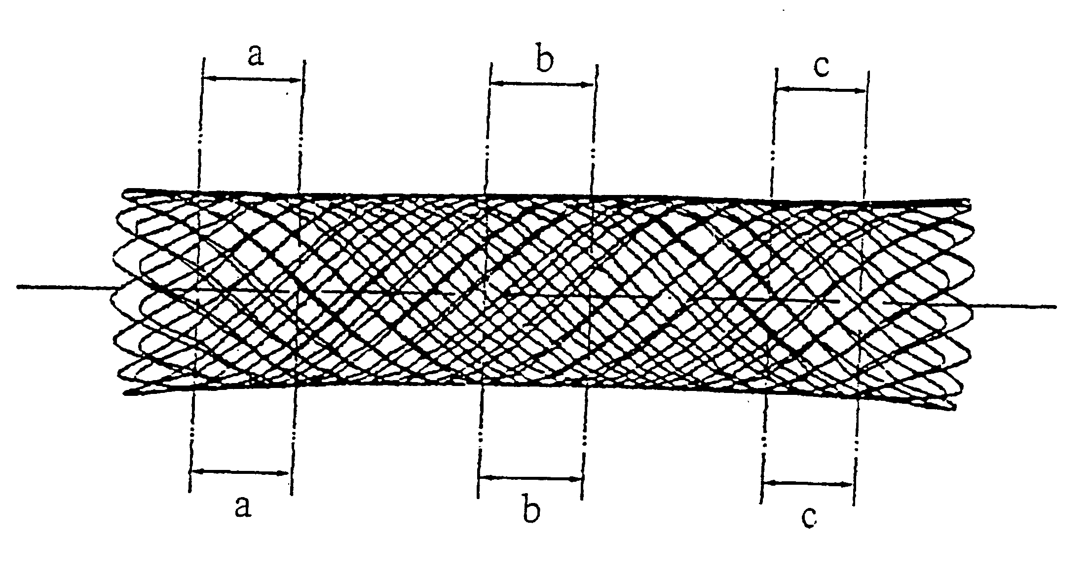
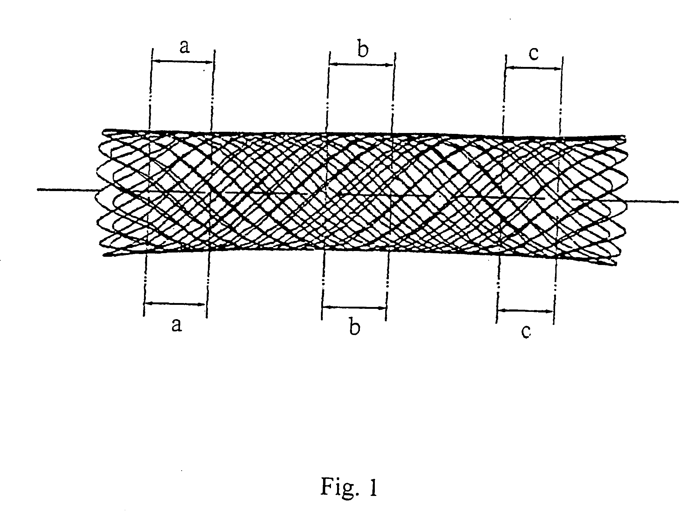
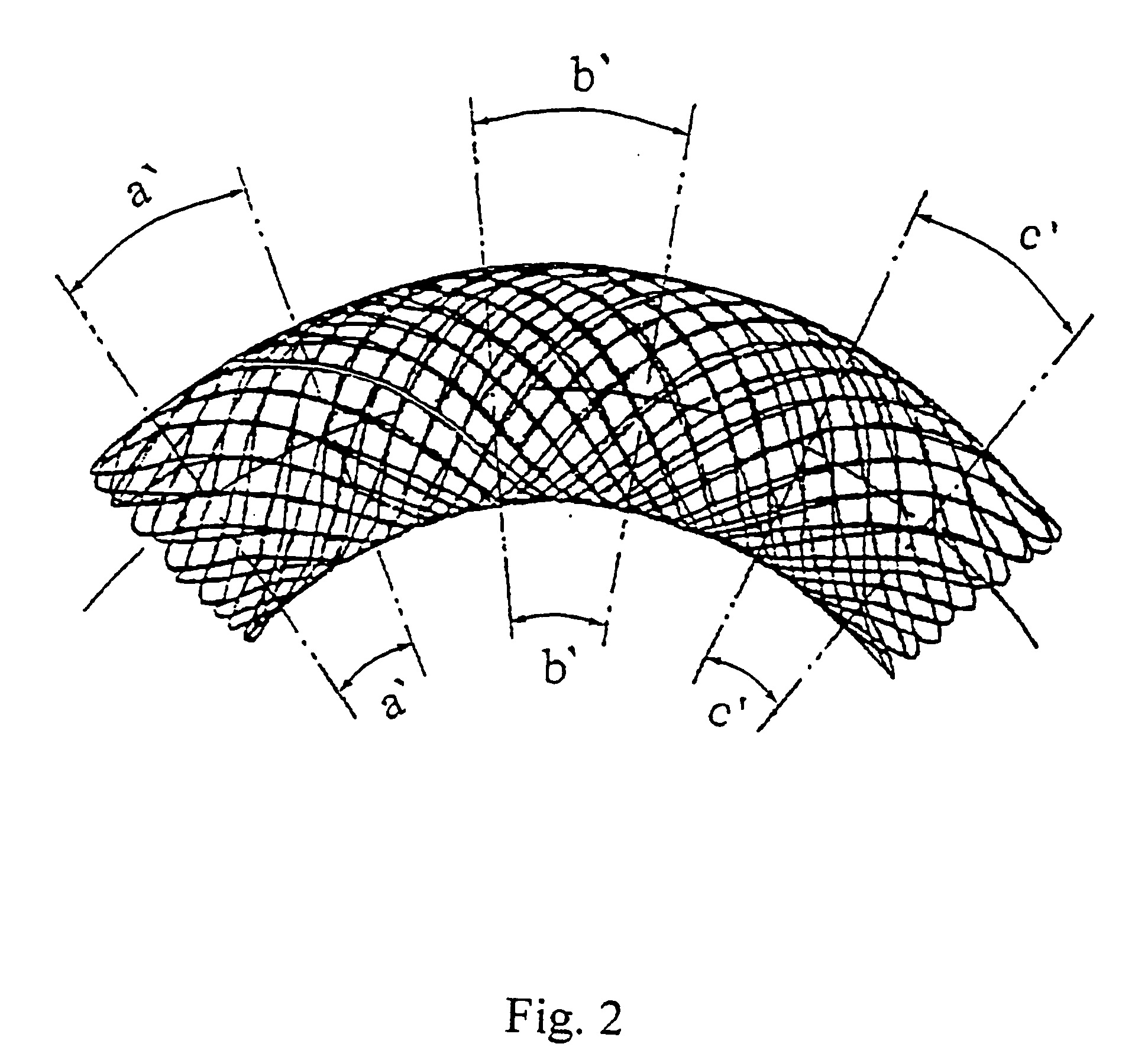
The inventions relate to the field of medicine and can be used in endoprosthetics for restoring a lumen in narrowed sections of vessels and other hollow organs. The stent is made as a netted hollow volumetric body, formed by interweaving of several groups of windings from a single length of a thread, placed along helical spirals with opposite entry directions. A material of the thread possesses elasticity and shape memory effect. Cells which are opposite with respect to the axis of the stent, are displaced with respect to each other, and the stoat thread has different elasticity in its separate sections, preserving the same thickness of the thread along the whole length of the stent. In the second variant of the stent its geometry is changed by way of making the stent with separate areas having a different axial curvature. The third variant of the stent unites the first and the second variants of the stent. In addition to that in all three variants the stent is manufactured from a medical nitinol Ti Ni. The method of stent manufacturing includes the formation of a netted hollow metallic body from a metallic thread by interweaving its windings, wound on a mandrel made as a body of revolution with a rectlinear longitudinal axis, and a pre-deformation of the stent on the mandrel by way of its quenching from the temperature 630-660° C. into water, which attributes a maximum elasticity to this stent. After the mandrel is removed the elasticity of separate sections of the stent is reduced, subjecting them to a secondary heat treatment at the temperature of 330-550° C. during from 1 to 30 minutes. In the rest variants of the method, the pre-deformation of the stent is conducted twice, first by way of primary heat treatment of the stent on the mandrel with a rectilinear longitudinal axis at the temperature of 330-390° C. during 5-20 minutes, and then on the mandrel with a curvilinear longitudinal axis, the form of which corresponds to the form of a prostheticated vessel. By that, by changing the time and temperature of the secondary heat treatment, the elasticity of the thread in separate sections of the stent and / or axial curvature of the stent are changed.

Description

FIELD OF THE ART [0001] The proposed invention relates to the field of medicine and can be used while making endoprostheses for restoring a lumen in narrowed sections of vessels and other hollow organs. PRIOR ART [0002] There is a great number of pathologies causing a stenosis or full on ion of vessels or other hollow org, as a result of which their functioning is partially or completely disturbed, which in its turn can be the reason of such serious diseases as insultus, infarctions, etc., up to a lethal outcome. [0003] A wide spreading of such types of diseases requires the development of effective methods for their treatment. One of such most widely spread method of treatment is the use of hollow endoprostheses, called stents. As a rule, they represent a hollow cylindrical body of revolution, which is introduced into a vessel or other hollow organ is fixed in a required place, and maintains a necessary lumen in an organ. [0004] The stents should satisfy to numerous requirement, so...

Claims


Application Information

Patent Timeline
Patent Type & Authority Applications(United States)
IPC IPC(8): A61F2/00A61F2/90
CPCA61F2250/0018A61F2/90
Inventor KOVNERISTY, JULY KGONCHARENKO, BORIS A.VYTOULEY, OLEG A.KULAPOV, ANATOLY K.CHERKASOV, VALERY A.IVANOV, ALEXEI V.PARTOSH, VICTOR T.
Owner KOVNERISTY JULY K
Learn More