Control apparatus for variable valve actuation system
- Summary
- Abstract
- Description
- Claims
- Application Information
AI Technical Summary
Benefits of technology
Problems solved by technology
Method used
Image

Examples
example 1
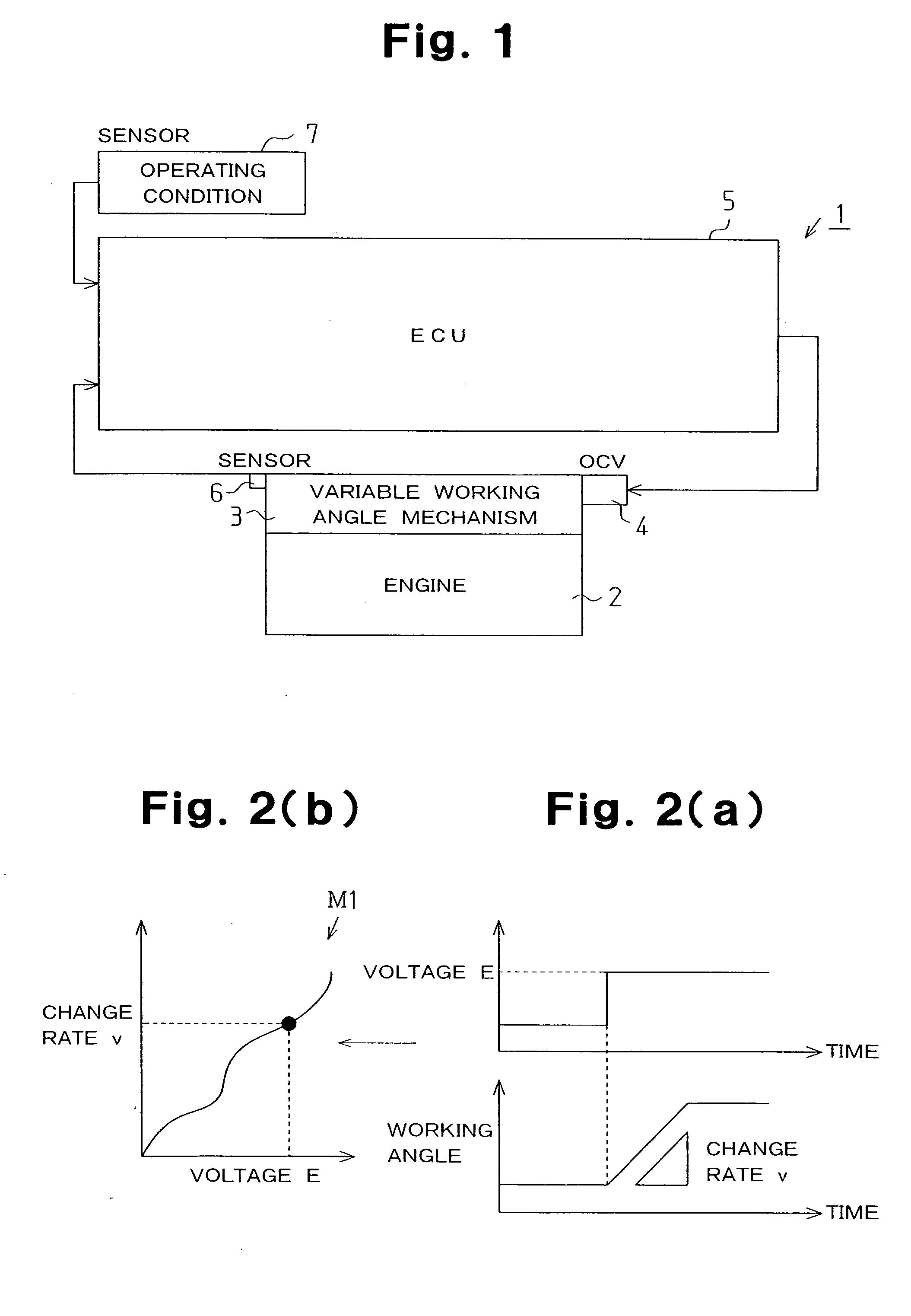
[0036] Hereunder, example 1 that embodies the control apparatus and method for a variable valve actuation system in accordance with the present invention will be described in detail with reference to the drawings. The variable valve actuation system 1 of example 1 has the ECU 5 as the control apparatus. The ECU 5 changes the working angle of valve in the variable valve actuation system by controlling the voltage supplied to the direct-current motor of the OCV 4.
[0037] In the upper graph in FIG. 2(a), the ordinate represents voltage E applied to the direct-current motor of the OCV 4 from the ECU 5, and the abscissa represents elapsed time. In the lower graph in FIG. 2(a), the ordinate represents the magnitude of working angle, and the abscissa represents elapsed time corresponding to the upper graph. FIG. 2(b) shows a map M1 representing the relationship between change rate v, which is a change amount per unit time of valve working angle, and voltage E.
[0038] When the voltage E is ...
example 2
[0055]FIG. 5 is a block diagram showing control of example 2. Hereunder, example 2 will be explained with reference to FIG. 5. The configuration of example 2 is almost the same as the configuration of example 1, but the configuration of map differs from the map M1 of example 1.
[0056] In the control apparatus of example 2, a map M2 prepared by determining the relationship between voltage E, change rate v, and engine speed R in advance is stored in the ROM. In addition to the voltage E, which is an anticipated control amount that is output to the OCV 4, and the change rate v, the engine speed R, which is a value of operating condition, is referred to. Therefore, by the storage means that stores the relationship between the anticipated control amount, the quantity of the valve state, and further the value of operating condition as a function or a map, anticipated control better suitable for the operating state is carried out.
[0057] In this example, the map M2 showing the relationship...
example 3
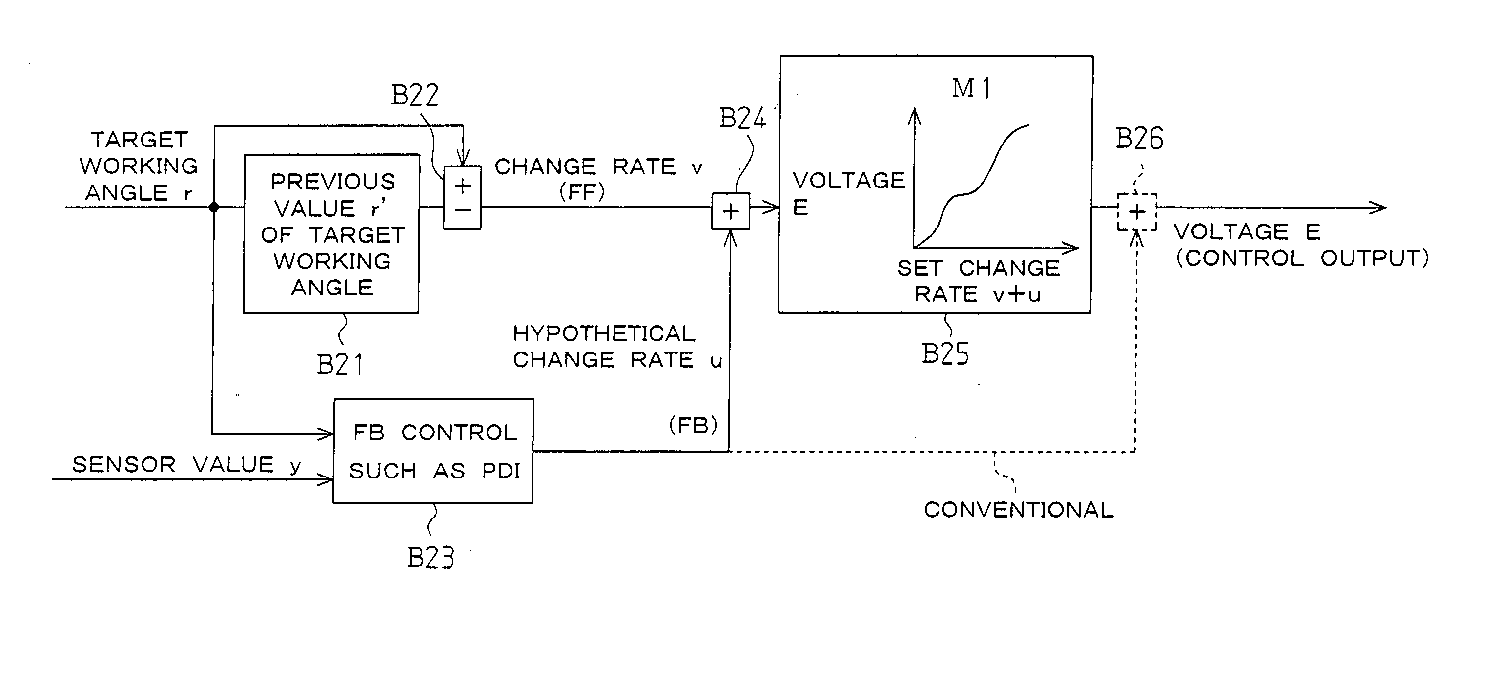
[0067] Next, example 3 that embodies the present invention will be described with reference to FIGS. 6 and 7. In example 3, an element of FB control is added on the basis of FF control of example 1. Basically, the portion of FF control is common to example 1, so that the detailed explanation of the common portion is omitted, and different points are mainly explained.
[0068]FIG. 6 is a flowchart showing a procedure for control of example 3, and FIG. 7 is a block diagram showing control of example 3. Hereunder, the procedure for control of example 3 will be explained by following the flowchart of FIG. 6 while referring to FIGS. 1 and 7.
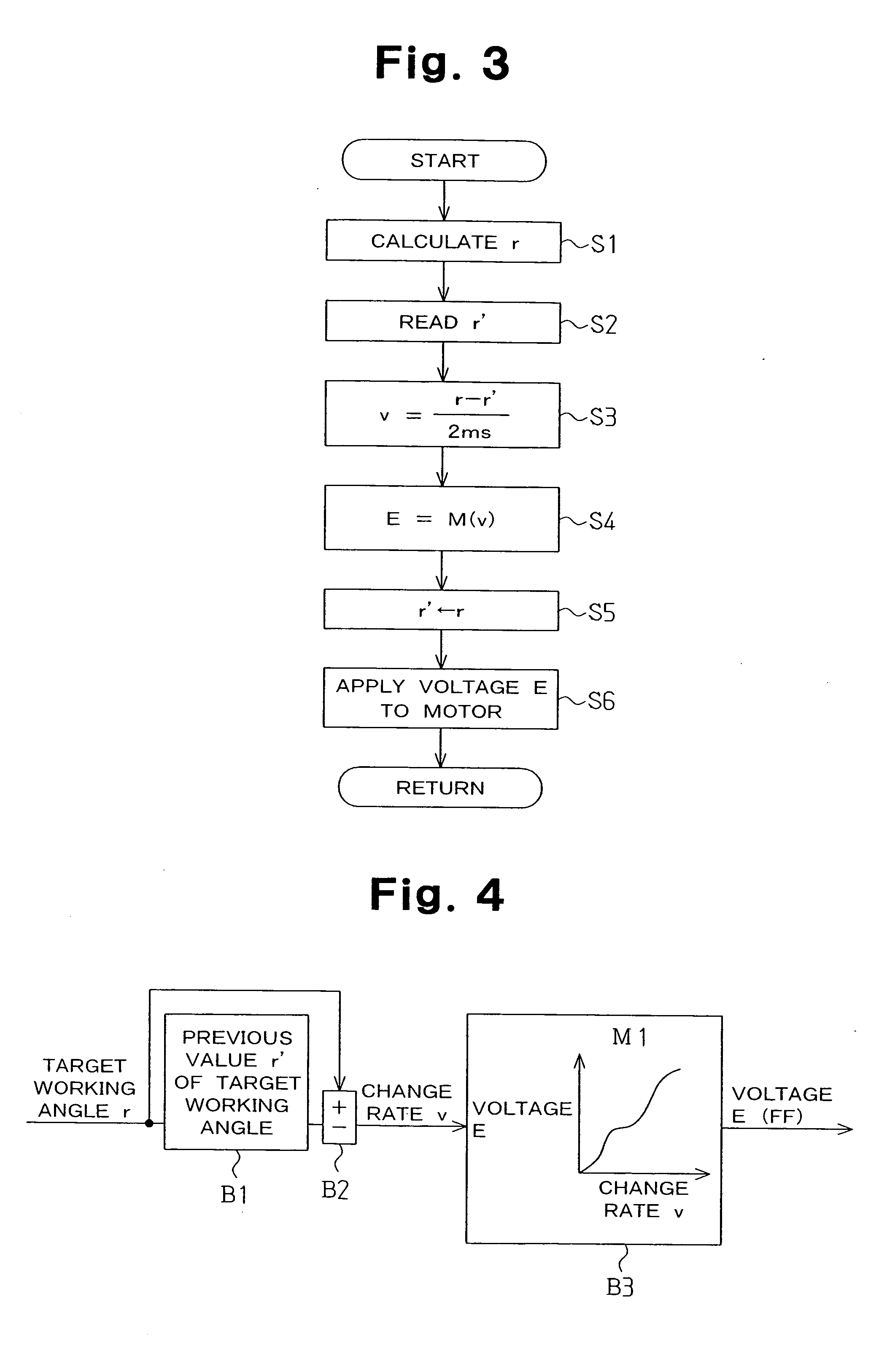
[0069] First, the ECU 5 calculates the target working angle r based on the data and program stored in the ROM by referring to the throttle opening degree and vehicle speed sent from the sensor 7 (S11). Succeedingly, the previous value r′ of target working angle stored in the RAM is read out (S12). Then, the change rate v is determined by the following ...
PUM
 Abstract
Description
Claims
Application Information
 - R&D
- Intellectual Property
- Life Sciences
- Materials
- Tech Scout
- Unparalleled Data Quality
- Higher Quality Content
- 60% Fewer Hallucinations
Browse by: Latest US Patents, China's latest patents, Technical Efficacy Thesaurus, Application Domain, Technology Topic, Popular Technical Reports.
© 2025 PatSnap. All rights reserved.Legal|Privacy policy|Modern Slavery Act Transparency Statement|Sitemap|About US| Contact US: help@patsnap.com