Enhanced computer optimized adaptive suspension system and method

a computer-optimized, adaptive suspension technology, applied in the direction of shock absorbers, valve operating means/release devices, servomotors, etc., can solve the problems of ineffective force applied to control movement in a direction opposite to movement, inability to regulate force in the rebound direction, lack of force, etc., to achieve the effect of alleviating instability problems and increasing fluid pressur

Inactive Publication Date: 2005-05-12
GREAT NORTHERN TECH
View PDF75 Cites 104 Cited by
  • Summary
  • Abstract
  • Description
  • Claims
  • Application Information

AI Technical Summary

Benefits of technology

[0017] The desired compression and rebound control forces for this set of parameters are determined, in part, by determining the amplitude of motion at the natural frequency of the sprung and unsprung mass systems. The natural frequency is isolated using an appropriate filter. Proportional damping forces in the direction opposite to the displacement of the spring from its normal or equilibrium position are determined and applied. A constant force is approximately maintained on the vehicle (emulating a constant force spring), thus minimizing body motions.
[0024] Since the area of the poppet annular shoulder exposed to the fluid pressure remains constant throughout the poppet stroke from a seated to a completely retracted position, the force generated by a given fluid pressure against the annular shoulder is constant tending to provide for a constant pressure regulation at different fluid flow rates. In other words, as the flow rate is increased, thereby increasing the fluid pressure, a larger force is reacted against the annular shoulder tending to retract the poppet further thereby canceling out the pressure created by the increased in fluid flow, thus, alleviating the instability problems associated with current valves incorporating poppets.
[0026] The movement of the poppet is stopped when a flange extending from the poppet engages an inner annular shoulder formed on the valve body. As a result, the valve body is not loaded by the tip of the poppet as with conventional poppet valves alleviating the need to use expensive hardened steel as is used in the valve body of a conventional poppet valve for enduring the pounding by the poppet tip.
[0028] The fluid control unit and specifically the control valves of the present invention provide for a smooth metering of fluid to and from the actuators without the need for the large and expensive accumulators. Moreover, the fluid control unit of the present invention has a LVIT position sensor integrated into the reservoir. Furthermore, the valves of the present invention provide for better operational stability, are smaller and less costly, have longer fatigue lives and incorporate an optimum conical tip angle for providing a flat pressure response over different flow rates.

Problems solved by technology

However, while a compression force is being applied and regulated it is not possible to regulate force in the rebound direction.
A problem with this design is that there is a lack of force when the direction of travel of the damper is wrong for the application of a control force.
This is because the direction of travel has changed, and forces applied to control movement in a direction opposite to the movement are ineffective.
Thus, control forces can be momentarily lost during damper movements in an undesired direction when attempting to maintain a constant force.
This loss of force is not as serious as what happens when the direction of movement one again engages the control valve and the previously preset pressure returns very abruptly, which results in severe harshness.
In addition in some applications a loaded vehicle's suspension becomes mushy.
In providing UNF forces a steep force causes a mechanical strain on the system hardware.
In the bottoming out and toping out force generation sufficient control was not obtained.
However, the use of mechanical parts to provide compliance increases the number of parts required for fabrication and assembly.

Method used


Image

  • Enhanced computer optimized adaptive suspension system and method
  • Enhanced computer optimized adaptive suspension system and method
  • Enhanced computer optimized adaptive suspension system and method

Examples


Embodiment Construction

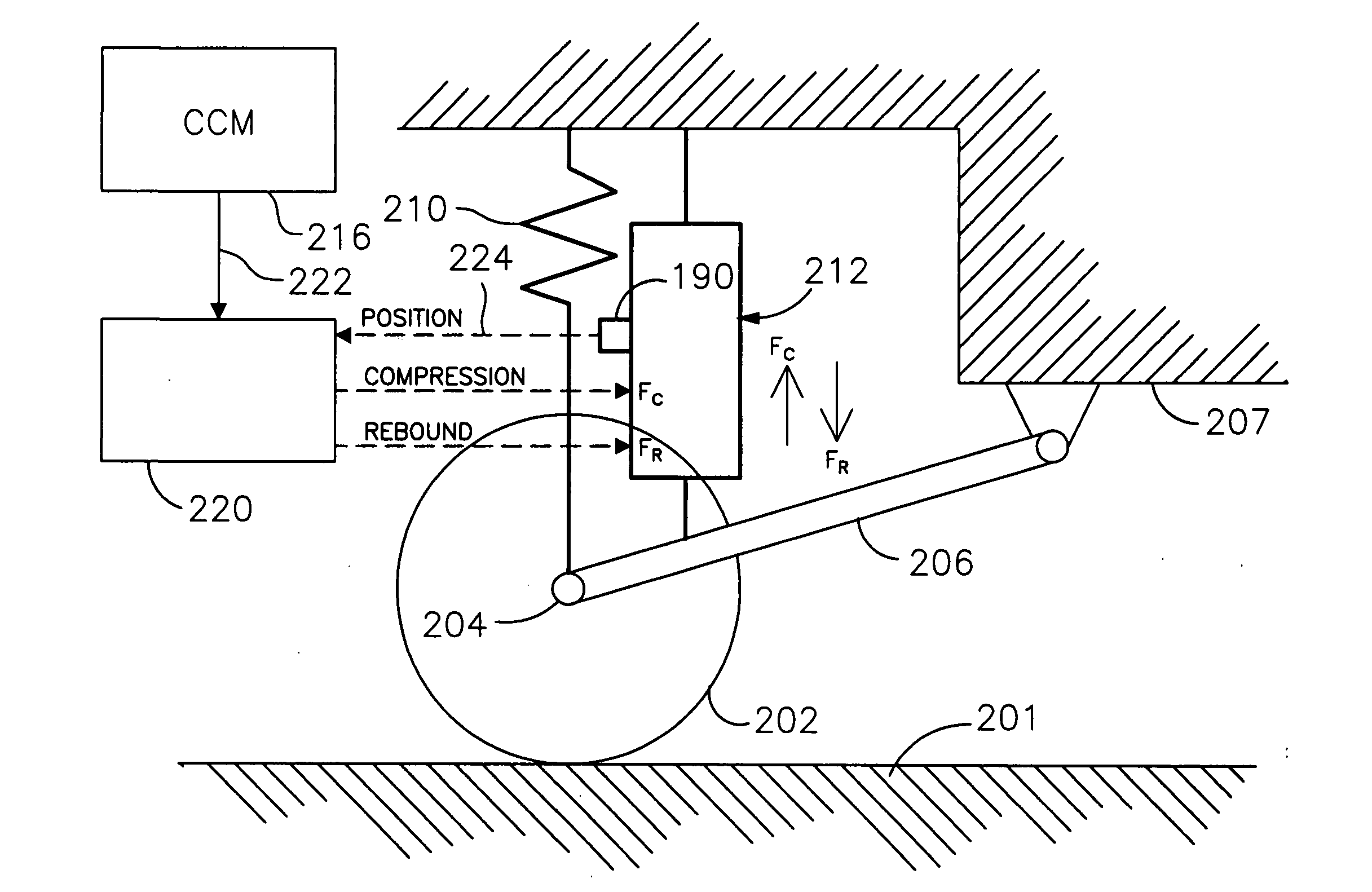
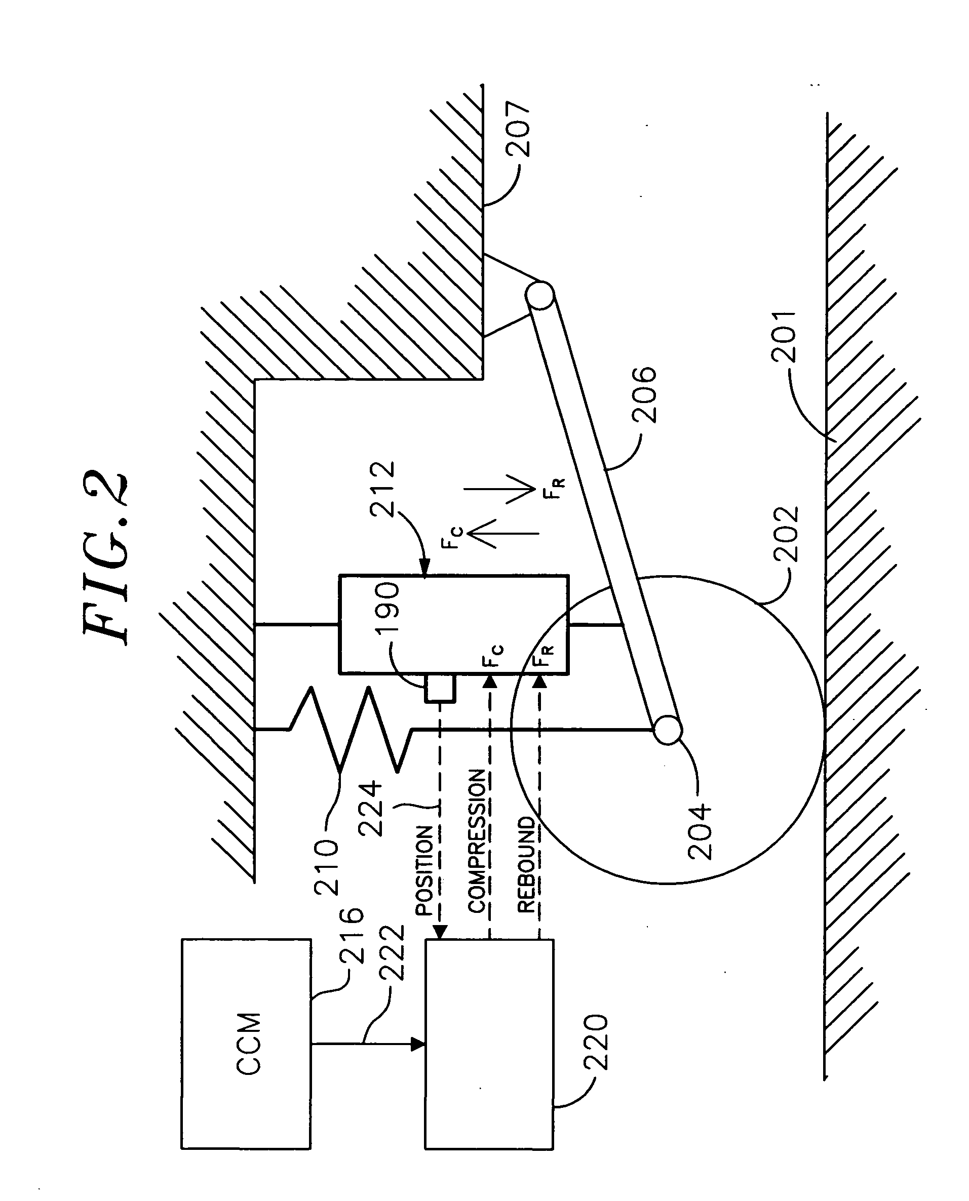
[0052]FIG. 2 illustrates one representative wheel 202 of a plurality of wheels in a suspension system in accordance with an embodiment of the present invention. The wheel rotates on an axle 204. The axle is attached to one end of a carrier 206. The other end of the carrier is pivotally mounted to a vehicle frame or chassis 207. It is understood that a variety of wheel mounting configurations may be used. A suspension control unit 212 and a spring 210 are connected between the chassis and axle.

[0053] The wheel, axle, and carrier comprise an unsprung mass, and the frame 207 comprises a sprung mass. During operation of the vehicle the wheel will often encounter irregularities in a road surface. For example, the wheel may encounter a bump in the road, with the result that the wheel is forced towards the chassis.

[0054] The wheel can move towards the chassis (compression) or away from the chassis (rebound). To change the characteristics of the ride, compression and rebound control force...


PUM


Abstract

A system and method for controlling a damping system. The system has at least two dampers for damping between sprung and unsprung masses in the compression and rebound directions. Sensors generate signals based on position and other parameters of motion representative of the displacement between the sprung and unsprung masses. The process determines the appropriate compression and rebound forces to be applied at the wheels. A regulator responds to at least one of the independent compression and rebound control signals for adjusting, respectively, at least one of compression and rebound resisting forces of the dampers between the masses. Compliance for the dampers is emulated with software to produce the desired compliance forces. The distributed controller includes a processor that is responsive to signals representative of the position signals for forming the compression and rebound control signals for the regulator as a function of motion between the masses or a motion of a vehicle in which the dampers are located. The system has the capability of locking the suspension when parked.

Description

CROSS-REFERENCE TO RELATED APPLICATION(S) [0001] This application is a Continuation application of U.S. patent application Ser. No. 10 / 205,205, filed on Jul. 24, 2002 which is a divisional of U.S. patent application Ser. No. 09 / 439,109, filed Nov. 11, 1999, which claims the benefit of U.S. Provisional Patent Application No. 60 / 107,999 filed Nov. 11, 1998, the disclosures of which are incorporated herein by reference.BACKGROUND OF THE INVENTION [0002] The present invention relates to computer controlled vehicle suspension systems and methods, and more particularly to vehicle suspension systems and methods in which computer controlled damping forces in compression and rebound directions are used to optimize ride and handling characteristics of the vehicle. [0003] A typical suspension system interlinks wheels and axles of the vehicle with the body and chassis of the vehicle. The suspension system generally includes springs and damping devices. The spring compress and expand to minimize...

Claims


Application Information

Patent Timeline
Patent Type & Authority Applications(United States)
IPC IPC(8): B60G17/015B60G17/018B60G17/019B60G17/04B60G17/08F15B11/028F16F9/46F16F9/50F16F15/02F16K15/08F16K31/06
CPCB60G17/0152Y02T10/90B60G17/019B60G17/0408B60G17/08B60G2202/413B60G2202/416B60G2204/111B60G2204/112B60G2206/41B60G2400/102B60G2400/25B60G2400/252B60G2401/26B60G2500/10B60G2600/184B60G2800/012F15B11/028F15B2211/40515F15B2211/41536F15B2211/426F15B2211/50572F15B2211/526F15B2211/6313F15B2211/6336F15B2211/6653F15B2211/7053F16F9/466B60G17/018
Inventor HAMILTON, JAMES M.WOODS, LONNIE K.
Owner GREAT NORTHERN TECH
Why Eureka
Try Eureka