Band elimination filter, filter device, antenna duplexer and communication apparatus

a filter device and filter technology, applied in the direction of electrical equipment, transmission, electromechanical/electrostrictive/magnetostrictive devices, etc., can solve the problems of difficult to provide characteristics of a high attenuation within a desired frequency range, and low loss over wide frequency bands

Inactive Publication Date: 2005-05-12
PANASONIC CORP
View PDF11 Cites 51 Cited by
  • Summary
  • Abstract
  • Description
  • Claims
  • Application Information

AI Technical Summary

Benefits of technology

[0022] The 3rd aspect of the present invention is the band elimination filter according to the 2nd aspect of the present invention, wherein a normalized impedance, which is obtained by normalizing the impedance of said reactance element with a characteristic impedance, is higher than 1.

Problems solved by technology

However, there cannot be provided a band elimination filter having a low loss over a wide band.
As described above, with the surface acoustic wave filter composed of a plurality of acoustic resonators, such as surface acoustic wave resonators, used in communication apparatus or the like, it has been difficult to provide characteristics of a high attenuation within a desired frequency range and a low loss over wide frequency bands lower and higher than a stop band.

Method used


Image

  • Band elimination filter, filter device, antenna duplexer and communication apparatus
  • Band elimination filter, filter device, antenna duplexer and communication apparatus
  • Band elimination filter, filter device, antenna duplexer and communication apparatus

Examples


embodiment 1

[0145] Now, a surface acoustic wave filter according to an embodiment 1 of the present invention will be described with reference to the drawings.

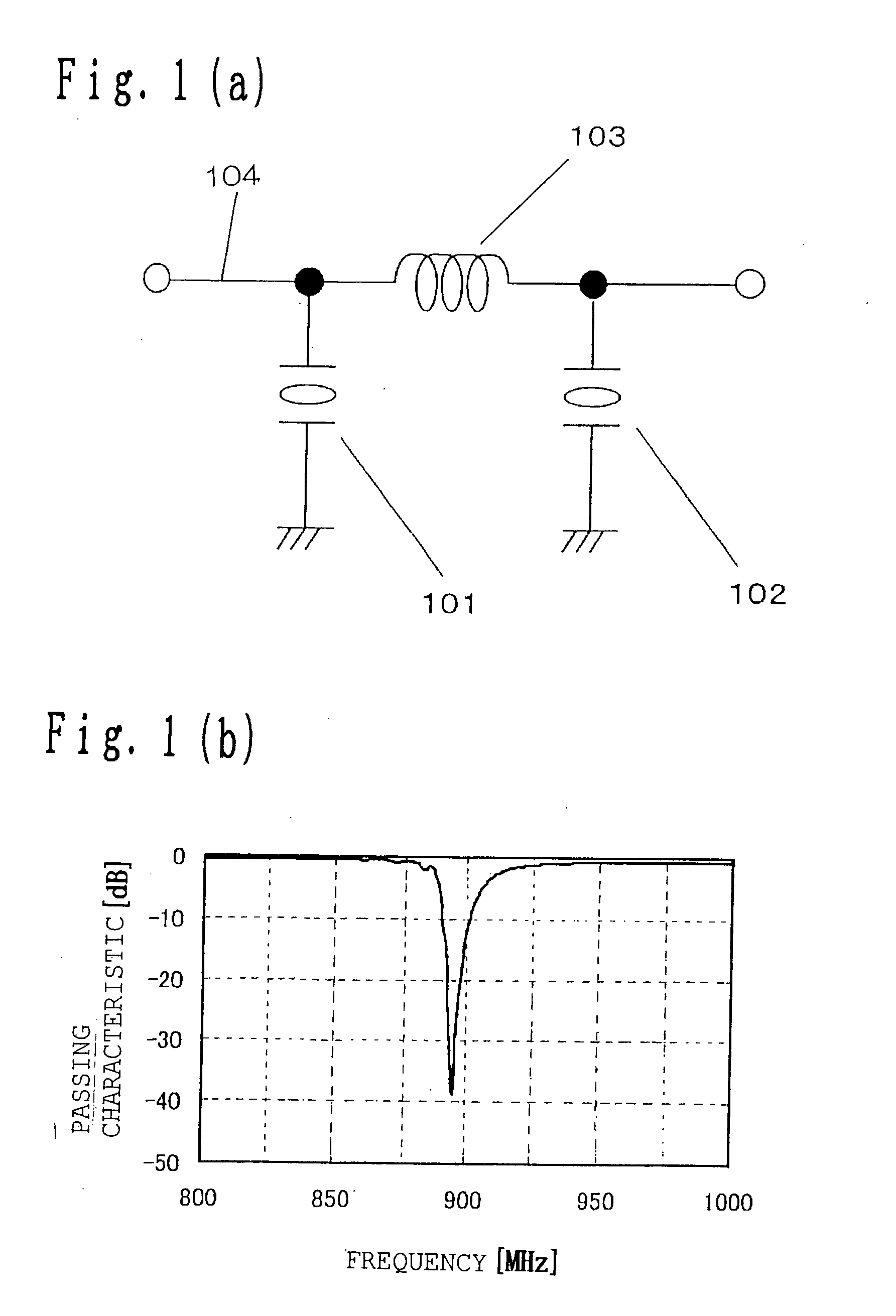
[0146]FIG. 1 shows a configuration of the surface acoustic wave filter and a passing characteristic according to the embodiment 1. In FIG. 1, FIG. 1(a) shows the configuration of the surface acoustic wave filter and FIG. 1(b) shows the passing characteristic. As shown in FIG. 1(a), the surface acoustic wave filter has first and second surface acoustic wave resonators 101 and 102 as acoustic resonators of the present invention and an inductor 103 as a reactance element of the present invention, which couples the resonators with each other. As shown in FIG. 19(a), the surface acoustic wave resonators 101, 102 each have an IDT electrode formed on a piezoelectric substrate, which is equivalent to a piezoelectric substrate according to the present invention, and reflector electrodes disposed on both sides thereof.

[0147] More specifically, the...

embodiment 2

[0155] In the following, a surface acoustic wave filter according to an embodiment 2 of the present invention will be described with reference to the drawings.

[0156] The surface acoustic wave filter according to the embodiment 2 has the same configuration as that of the embodiment 1, except that the surface acoustic wave resonators 101 and 102 constituting the surface acoustic wave filter have different resonance frequencies. That is, the surface acoustic wave resonators 101 and 102 have different pitches of IDT electrodes, and as a result, they have different resonance frequencies and antiresonance frequencies.

[0157]FIG. 3(a) shows a passing characteristic in the vicinity of a frequency of 900 MHz provided when the inductance value of the inductor is 8 nH. For comparison, FIG. 3(b) shows a passing characteristic in the vicinity of a frequency of 900 MHz provided in the case where the two surface acoustic wave-resonators 1901 and 1902 in the circuit in the conventional example 2 h...

embodiment 3

[0161] In the following, a surface acoustic wave filter according to an embodiment 3 will be described with reference to the drawings.

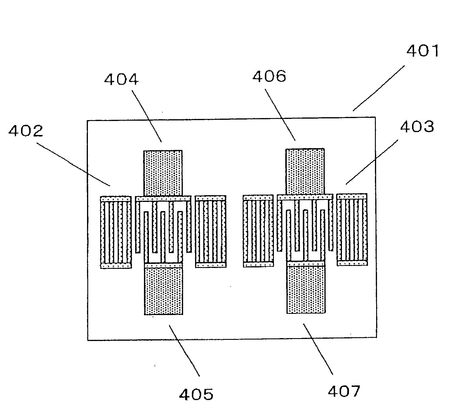
[0162]FIG. 4 shows a configuration of a part of the surface acoustic wave filter according to the embodiment 3 which is formed on a piezoelectric substrate. In FIG. 4, the part of the surface acoustic wave filter formed on the piezoelectric substrate is composed of first and second surface acoustic wave resonators 402 and 403 formed on a piezoelectric substrate 401, which is corresponding to the piezoelectric substrate of the present invention. An IDT electrode of the first surface acoustic wave resonator 402 is provided with electrode pads 404 and 405, and an IDT electrode of the second surface acoustic wave resonator 403 is provided with electrode pads 406 and 407.

[0163]FIG. 5(a) shows a configuration of the whole of the surface acoustic wave filter, according to this embodiment. In the surface acoustic wave filter shown in FIG. 5(a), the electrod...


PUM


Abstract

It has been difficult to provide a band elimination filter having characteristics of a high attenuation within a desired stop band and a low loss over wide frequency bands higher and lower than the stop band. A band elimination filter includes: a plurality of acoustic wave resonators as an acoustic resonator each having one end grounded; and a transmission line to which the other end of each of the plurality of acoustic wave resonators as an acoustic resonator is connected, in which at least some of the other ends are coupled to the transmission line at predetermined intervals, and at least one inductor is provided on transmission line in all or some of the predetermined intervals.

Description

BACKGROUND OF THE INVENTION [0001] 1. Field of the Invention [0002] The present invention relates to a band elimination filter or the like used in a communication apparatus, such as a cellular phone and car phone. [0003] 2. Related Art of the Invention [0004] Conventionally, a surface acoustic wave filter or piezoelectric filter has been used as an RF filter in communication apparatus. The surface acoustic wave filters mainly used include a longitudinal coupled mode filter having a plurality of interdigital transducer electrodes (IDT electrodes) closely arranged in the propagation direction and a ladder filter having surface acoustic wave resonators interconnected in a ladder-like arrangement. On the other hand, as the piezoelectric filter, a bulk wave filter is used. These filters are expected to be increased in performance and reduced in size. [0005] In the following, a conventional band elimination filter will be described with reference to the drawings. [0006]FIG. 19(a) shows a ...

Claims


Application Information

Patent Timeline
Patent Type & Authority Applications(United States)
IPC IPC(8): H03H3/02H03H9/02H03H9/05H03H9/56H03H9/60H03H9/64H03H9/72H04B1/44
CPCH03H9/02118H03H9/0542H03H9/6483H03H9/564H03H9/6409H03H9/0557H03H9/542H03H9/547
Inventor NAKAMURA, HIROYUKISEKI, SHUN-ICHIONISHI, KEIJI
Owner PANASONIC CORP
Why Eureka
Try Eureka