
Recording apparatus

a recording device and recording technology, applied in the field of recording devices, can solve the problems of reducing the control process speed of the recording device, affecting the output speed of the scanner-equipped printer, and affecting the quality of the recording, so as to reduce the occurrence of buffering, enhance throughput, and high-speed output

Active Publication Date: 2005-05-12
SEIKO EPSON CORP
View PDF0 Cites 30 Cited by
  • Summary
  • Abstract
  • Description
  • Claims
  • Application Information

AI Technical Summary

Benefits of technology

[0018] The present invention has been made in view of the foregoing problems, and an object thereof is to provide a recording apparatus in which recording data can be transferred to a recording head without using a CPU bus and that can realize high-speed output by reducing occurrence of buffering as much as possible, enhancing throughput, reducing the amount of data processed by a layout section, and increasing processing speed in layout processing and recording speed.
[0019] Further, another object is to provide a recording apparatus having high operability for when a plurality of images are to be arranged on paper.

Problems solved by technology

Further, conversion from the RGB image data to the print data is a process carried out by the CPU according to software, and since data are exchanged via the bus even during this process, an extremely large amount of data flows through the bus.
That is, there has been a problem that, if the traffic in the bus is heavy, then the control process speed of the apparatus drops, and therefore, the output speed of the scanner-equipped printer becomes slow.
Buffering is a state that occurs when all of the image data cannot be stored in the image data storage area, and this occurs when there is a delay in a process of outputting the image data stored in the image data storage area to, for example, a host computer or a process of converting the image data into print data.
Particularly, when the read resolution for reading an original is set high, the data amount of the image data that are generated becomes extremely large, and therefore, the number of times buffering occurs becomes large.
If the amount of data to be processed by the CPU increases, the speed of other processes of the CPU drops, and as a result, the print speed drops.
Since the layout processing requires complicated computations, it is not realistic to make the above-mentioned control circuit to perform even the layout processing.

Method used

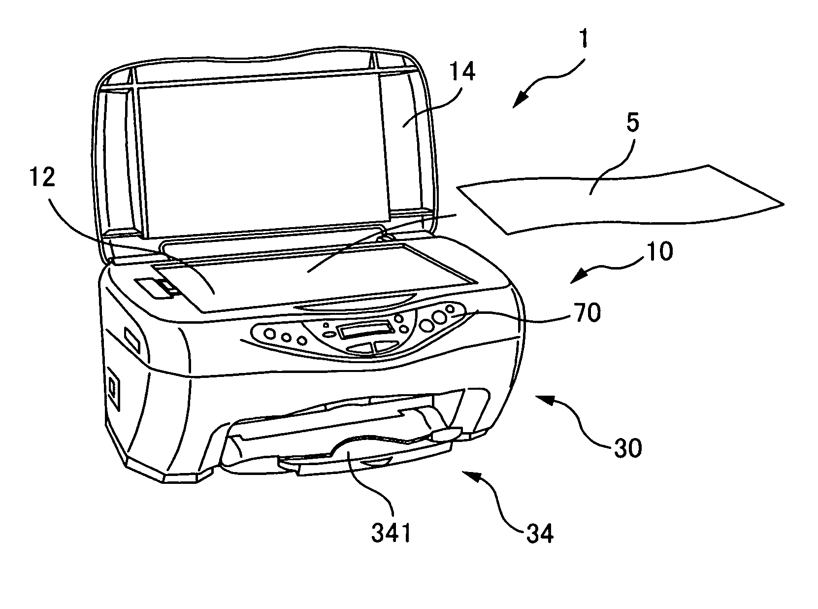
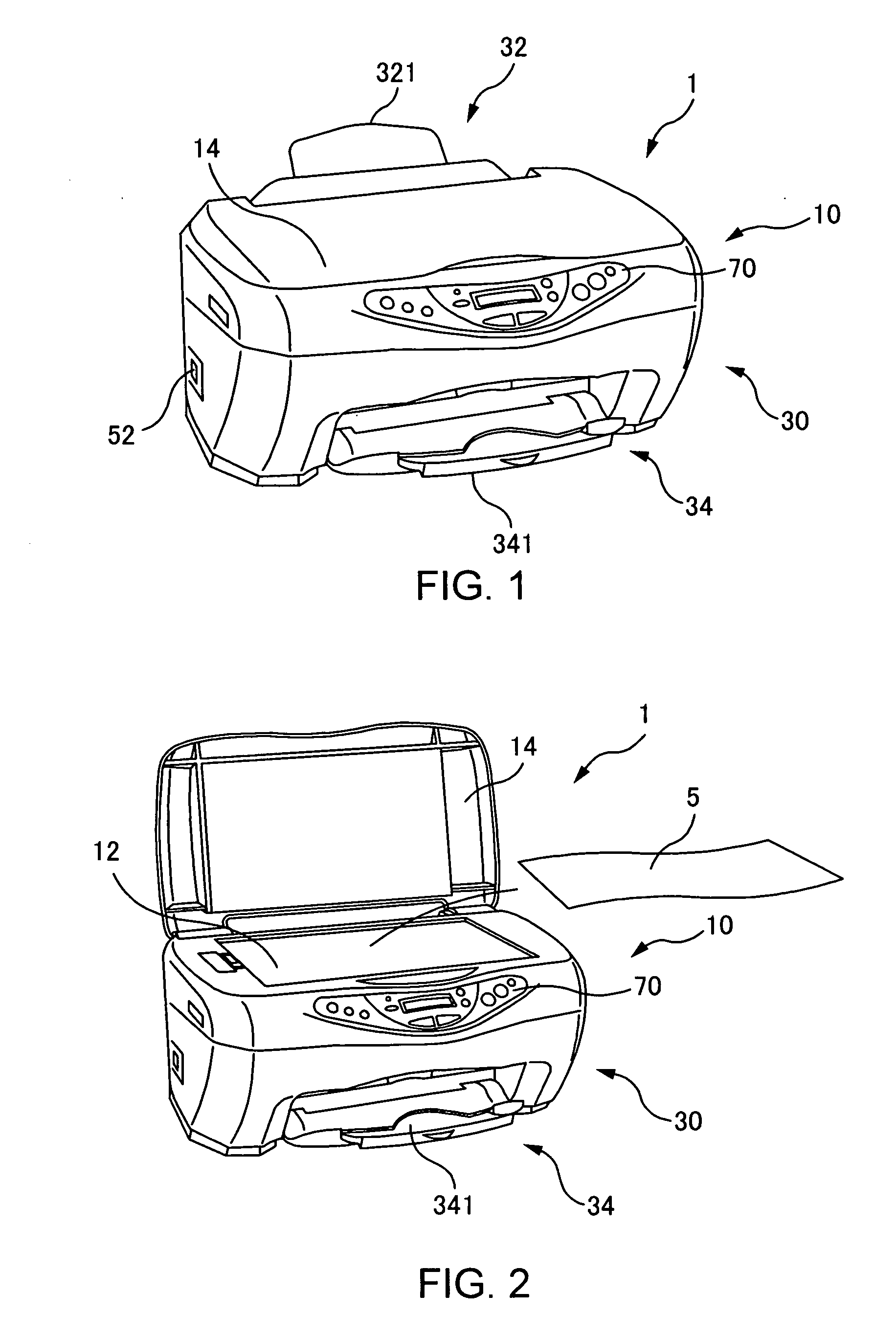
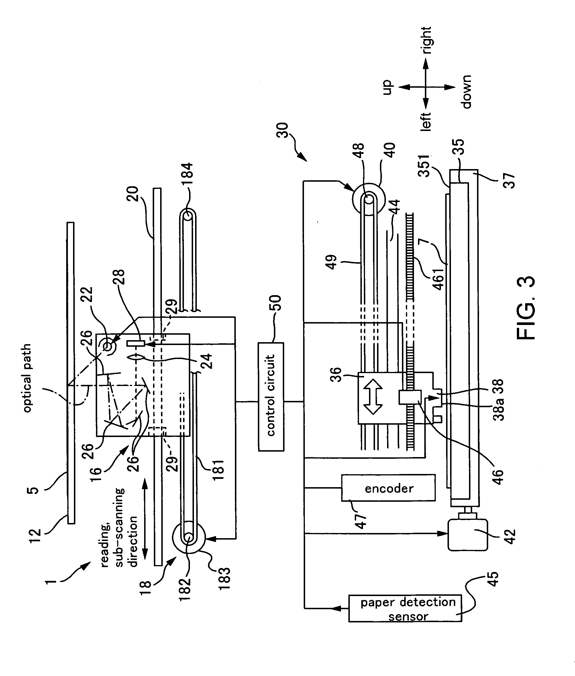

Image

  • Recording apparatus
  • Recording apparatus
  • Recording apparatus

Examples


first embodiment

of Repeat Printing

About the Data Flow in Control Circuit 50 when Repeat Printing is Performed

[0266]FIG. 23 is a block diagram showing an example of the control circuit 50 when repeat printing is performed. In FIG. 10 described above, two buffers —the image buffers 571, 572 (or the image buffers 694, 695)— were depicted for alternately performing writing and reading. In FIG. 23, however, in order to simplify the description, the two buffers for alternately performing writing and reading are not depicted.

[0267] Although the hardware configuration is the same as the control circuit 50 in FIG. 10 described above, the allocation of the memory area in the SDRAM 56, which is directly readable from the CPU 54, is different, for example. Further, in FIG. 10 described above, the CPU 54 accessed only the image buffers 694, 695. In FIG. 23, however, the CPU 54 also accesses the line buffer 691 and the interlace buffer 693. Further, the memory area allocation of the interlace buffer 693 is div...

second embodiment

in Repeat Printing

Internal Structure of the Control Circuit 50 in the Second Embodiment

[0298]FIG. 26 is a block diagram showing an example of a control circuit 50 of the second embodiment.

[0299] In the control circuit 50 of the SPC multifunction apparatus 1 of the second embodiment, the CPU 54 that manages the control over the entire SPC multifunction apparatus 1, a ROM 55 that stores a program for executing the control, the control ASIC 51 that manages the control over the scanner function, the printer function, and the local copier function, an SDRAM 56 in which data is directly readable and writable from the CPU 54, and the control panel section 70 serving as the input means are connected via the CPU bus 501. The scanner unit 10, the print head 38, the ASIC-SDRAM 69 in which data are directly readable and writable from the control ASIC 51, and so forth, are connected to the control ASIC 51.

[0300] The control ASIC 51 includes the scanner control unit 58, a re-sizing unit 59, th...


PUM


Abstract

A recording apparatus, and so forth, capable of outputting at high speed is provided. Second recording data that are stored in a memory based on data obtained by a data obtaining section are transferred to a data generator via a second transfer path, and based on the second recording data that have been transferred, the data generator generates first recording data for performing recording on a medium.

Description

CROSS-REFERENCE TO RELATED APPLICATIONS [0001] The present application claims priority upon Japanese Patent Application No. 2002-290404 filed Oct. 2, 2002, Japanese Patent Application No. 2002-290405 filed Oct. 2, 2002, Japanese Patent Application No. 2003-111331 filed Apr. 16, 2003, Japanese Patent Application No. 2003-329167 filed Sep. 19, 2003, and Japanese Patent Application No. 2002-288977 filed Oct. 1, 2002, which are herein incorporated by reference. BACKGROUND OF THE INVENTION [0002] 1. Field of the Invention [0003] The present invention relates to recording apparatuses for recording according to recording data. [0004] 2. Description of the Related Art [0005] Scanner-equipped printers that have scanner sections for taking in original images and printer sections for performing printing according to the supplied print data are known as an example of recording apparatuses that perform recording according to recording data. In scanner-equipped printers, a CPU that takes control ...

Claims


Application Information

Patent Timeline
Patent Type & Authority Applications(United States)
IPC IPC(8): H04N1/32
CPCH04N1/00416H04N1/32512H04N1/32561H04N2201/3297H04N1/32593H04N2201/0091H04N1/32587
Inventor YADA, JUNYATAKAHASHI, TOMOHIROONO, KOICHIMIYAZAWA, SHUNSAKUKATAYAMA, TOSHIHIKONARUSAWA, HIDEYUKI
Owner SEIKO EPSON CORP
Learn More