
Illumination optical system and exposure apparatus having the same

a technology of illumination optical system and exposure apparatus, which is applied in the field of illumination optical system, can solve the problems of reducing the transmittance disadvantageously, increasing the cost by gaining the number of lens elements, and not being able to make the fly-eye lens easy to work

Inactive Publication Date: 2005-05-12
CANON KK
View PDF12 Cites 10 Cited by
  • Summary
  • Abstract
  • Description
  • Claims
  • Application Information

AI Technical Summary

Benefits of technology

[0012] An illumination optical system according to one aspect of the present invention for Koehler-illuminating a target surface with light from a light source includes a light integrator for forming a secondary light source, the light integrator including plural e

Problems solved by technology

Shortening the wavelength of exposure light can cause an increased absorption in an optical material, such as a glass material and optical coating, lowering the transmittance disadvantageously.
However, the lens elements are an independent lens respectively, so the cost increases by gaining the numbers of the lens elements.
Moreover, it is not easy working to make the fly-eye lens that arranged the lens elements by the common difference of corresponding.
However, the unitary-type fly-eye lens has a problem in that the uniform illumination distribution cannot necessarily be formed.
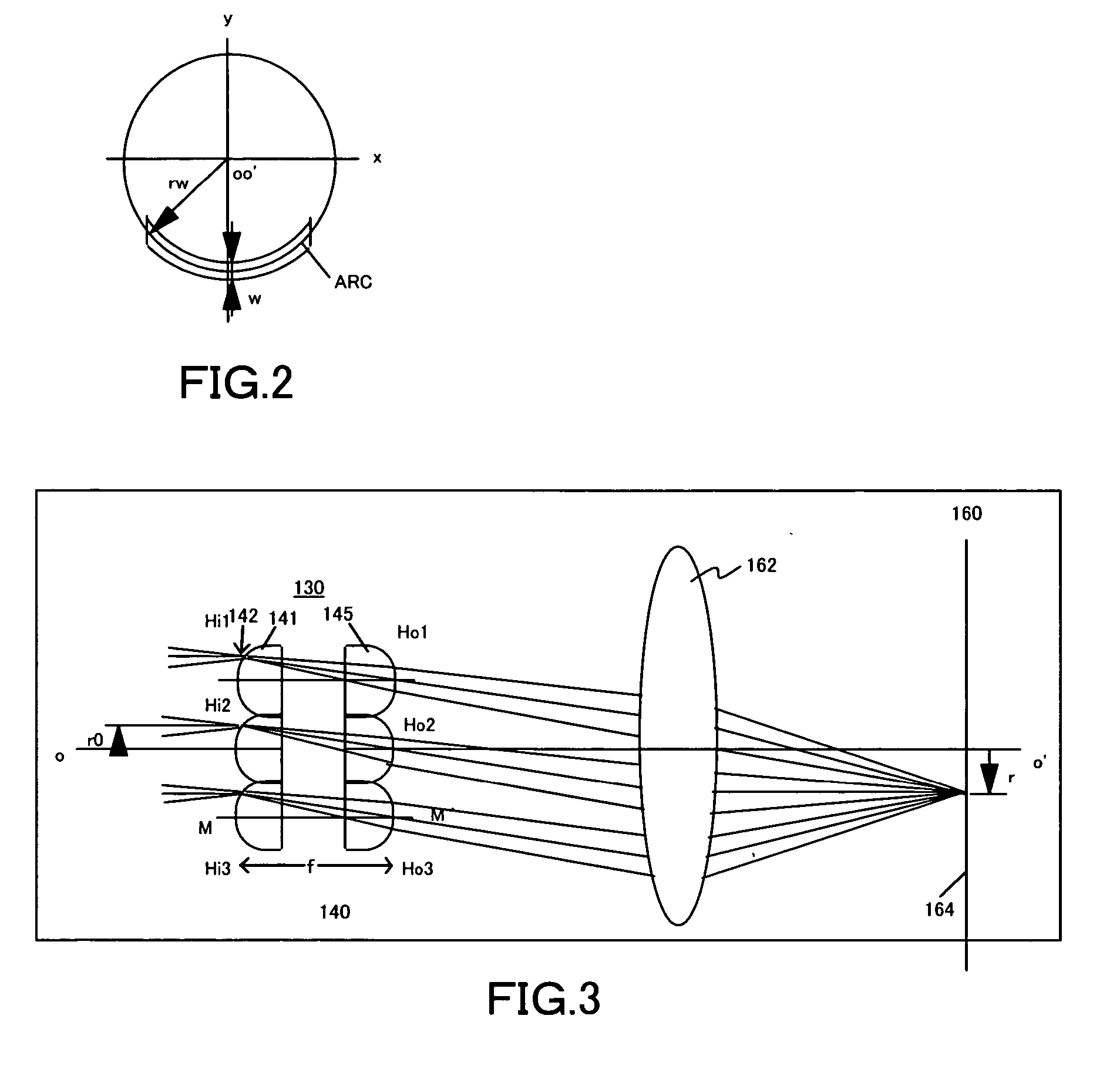
This step does not contribute to uniform mask illumination, and the light that passes through the step goes straight.
The condensing point forms an abnormal point, which is called a hot spot, causes non-uniform light intensity.
In other words, the hot spot makes the light intensity distribution non-uniform on the illuminated surface.
This results in an abnormal integral exposure dose in the exposure plane and an abnormal critical dimension in the circuit pattern, decreasing the yield.
The unitary-type reflection optical integrator that directly forms fine reflective elements on the substrate has a similar problem.

Method used


Image

  • Illumination optical system and exposure apparatus having the same
  • Illumination optical system and exposure apparatus having the same
  • Illumination optical system and exposure apparatus having the same

Examples


Embodiment Construction

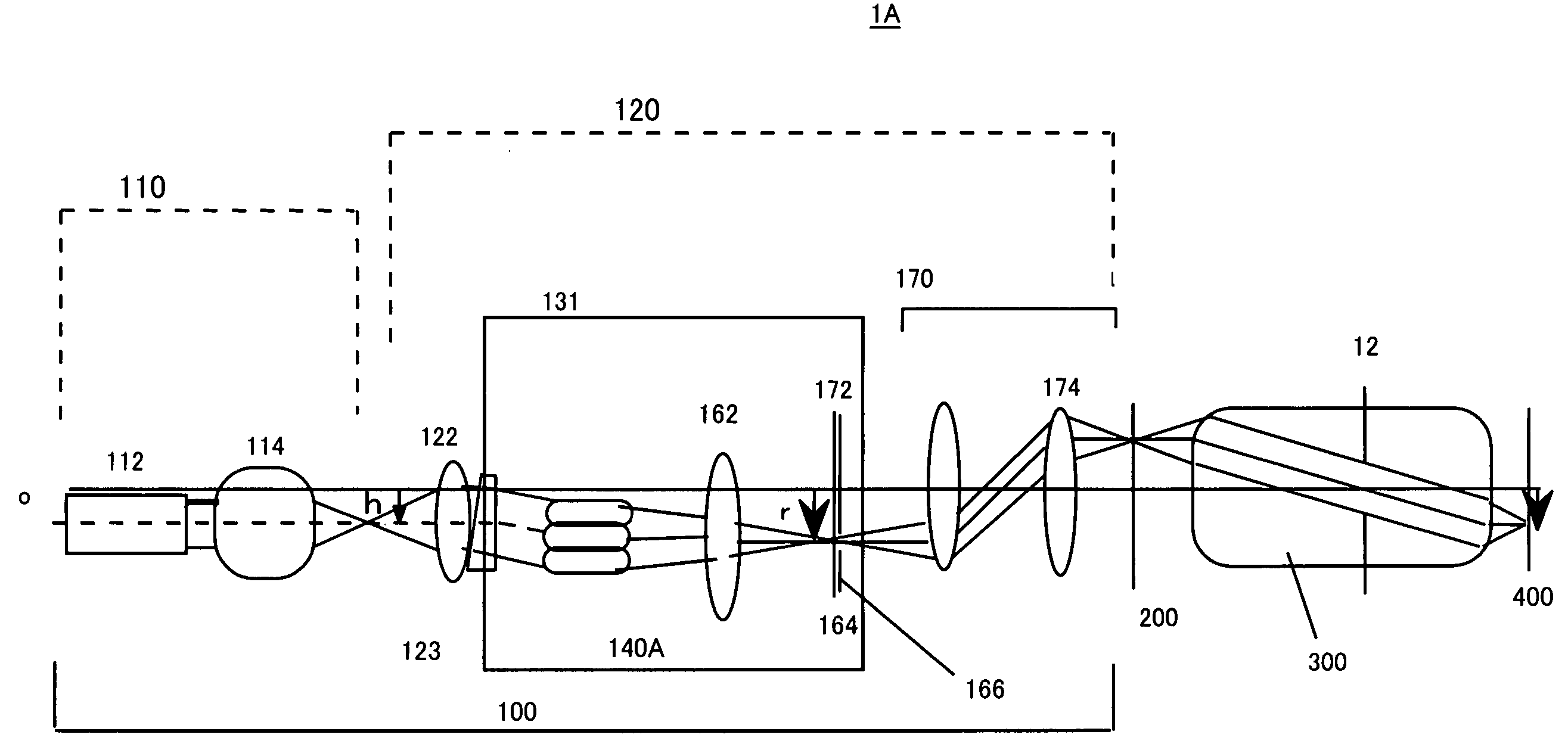
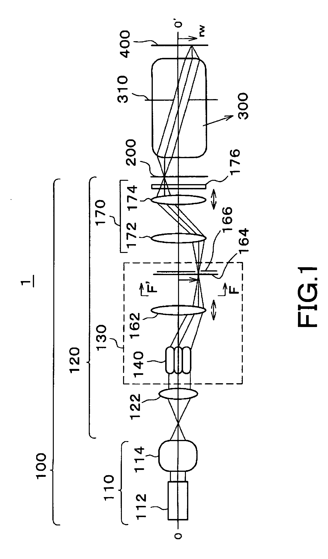
[0034] With reference to the accompanying drawings, a description will be given of an exposure apparatus 1 of the instant embodiment. A detailed description will now be given of the exposure apparatus 1, with reference to FIG. 15. Here, FIG. 15 is a schematic view of a simplified optical path of the exposure apparatus 1. The exposure apparatus includes an illumination apparatus 100, a mask 200, a projection optical system 300, and a plate 400.

[0035] The exposure apparatus 1 of this embodiment is a projection exposure apparatus that exposes a circuit pattern created on the mask 200 in a step-and-scan manner onto the plate 400, but the present invention can apply a step-and-repeat manner and other modes of exposure method. The “step-and-scan” manner, as used herein, is one mode of exposure method that exposes a mask pattern onto the plate by continuously scanning the plate relative to the mask and by moving, after a shot of exposure, the plate stepwise to the next exposure area to be...


PUM


Abstract

An illumination optical system for Koehler-illuminating a target surface with light from a light source includes a light integrator for forming a secondary light source, the light integrator including plural elements formed directly onto a substrate; a condenser for condensing the light from the light integrator; and a shield for shielding the light that goes straight in interfaces among the plural elements from an effective illumination area on the illuminated surface.

Description

BACKGROUND OF THE INVENTION [0001] The present invention relates generally to an exposure apparatus, and more particularly to an illumination optical system for uniformly illuminating a reticle (or a mask) which has a pattern, in an exposure apparatus used in a photolithography process for fabricating semiconductor devices, liquid crystal display devices, image pick-up devices (CCD, and the like), thin-film magnetic heads, and the like. [0002] Recently, a manufacture of finer semiconductor devices has increased demands for high throughput with a design rule for a mass production line of 130 nm. The fine processing with improved resolution requires the uniform light intensity for illuminating a reticle or a mask and the uniform effective light-source distribution as an angular distribution of the exposure light for illuminating the reticle (or mask) as well as a shortened wavelength of exposure light and a higher numerical aperture (“NA”) of a projection lens. [0003] Shortening the w...

Claims


Application Information

Patent Timeline
IPC IPC(8): G03F7/20F21V1/00H01L21/027
CPCG03F7/70075
Inventor KOHNO, MICHIO
Owner CANON KK
Learn More