
Optical disk device and method of recording optical data

a technology of optical disk and optical data, which is applied in the direction of digital signal error detection/correction, instruments, television systems, etc., can solve the problems of inability to prepare write strategies appropriate for all optical disks currently distributed in the market, and the drive manufacturer requires various processes and a lot of time to optimize write strategies, etc., to achieve optimal write strategies

Active Publication Date: 2005-05-12
SAMSUNG ELECTRONICS CO LTD
View PDF4 Cites 41 Cited by
  • Summary
  • Abstract
  • Description
  • Claims
  • Application Information

AI Technical Summary

Benefits of technology

[0017] Accordingly, the present invention has been made keeping in mind the above problems occurring in the prior art, and an object of the present invention is to provide an optical disk device and an optical information recording method, which is capable of setting optimum parameters on an optical disk being used in a short time without using a specific recording pattern.
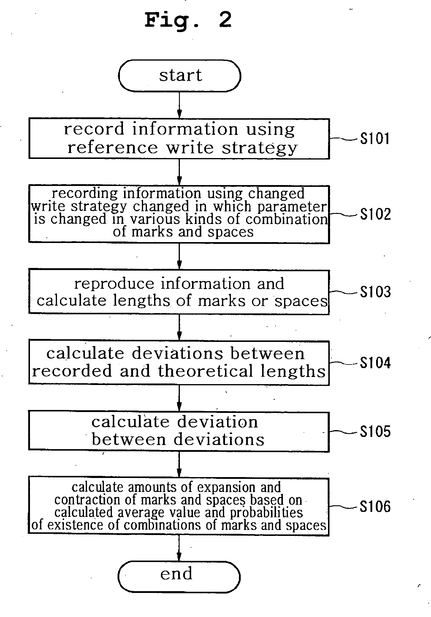
[0020] In accordance with the above-described inventions, since the unique amounts of expansion and contraction of the marks and the spaces based on the deviations between the lengths of the marks and the spaces recorded using the reference strategy, the lengths of the marks and spaces using the changed write strategy in which at least one setting parameter is changed in a plurality of kinds of the combinations of the marks and the spaces, and theoretical lengths of the marks and the spaces, and the probabilities of existence of the marks and the spaces, the unique amount of expansion and contraction for each of the optical information recording media can be quickly learned in the case where information is recorded by two recording operations using the same write strategy.
[0025] In accordance with the above-described inventions, with the sequence determination means, the sequence of determination of the unique amounts of expansion and contraction of the marks and the spaces can be determined based on deviations in front of and behind edges when the information is recorded using the reference write strategy and the jitter values of the signals recorded using the changed write strategy in which setting parameters are changed, so that the difference between the results can be reduced and the optimum processing sequence can be determined when two or more parameters has been changed.
[0028] In accordance with the above-described invention, a correction value for the reference write strategy is calculated based on the unique amounts of expansion and contraction of the marks and the spaces and the probabilities of existence so as to allow the deviations of the marks and the spaces to fall within a predetermined range, so that the optimum write strategies can be quickly set on all optical recording media with the deviations of other marks and spaces taken into consideration.
[0031] In accordance with the above-described inventions, the calculation of the correcting values is performed in the ascending sequence of the probability of existence that influences other marks and spaces, and thus optimum write strategies can be quickly set on all optical information recording media.

Problems solved by technology

However, since a problem arises in that a mark is undesirably formed due to the heat accumulation and short cooling rate of an optical disk attributable to the difference in the composition of a dye recording layer constituting the optical disk, desired marks and spaces are not formed when the EFM signals are recorded.
Accordingly, a drive manufacturer requires various processes and a lot of time to optimize the write strategy.
Additionally, numerous kinds of optical disks that even the drive manufacturing companies are not aware of are sold commercially.
Accordingly, it is impossible to prepare write strategies appropriate for all the optical disks currently distributed in the markets.
The former method is problematic in that the write strategy finally selected is just the best write strategy in the set write strategies, so that the selected write strategy cannot always be an optimum write strategy.
Furthermore, another problem arises in that only a recording region required for a test uses tracks.
Furthermore, the latter method is problematic in that in view of the use of a specific recording pattern, when a specific mark or space is changed, an influence on other marks and spaces are not taken into consideration, so that it is impossible to-set an optimum write strategy on, an optical disk being used through a single recording and reproducing test.

Method used


Image

  • Optical disk device and method of recording optical data
  • Optical disk device and method of recording optical data
  • Optical disk device and method of recording optical data

Examples


Embodiment Construction

[0045] Reference now should be made to the drawings, in which the same reference numerals are used throughout the different drawings to designate the same or similar components.

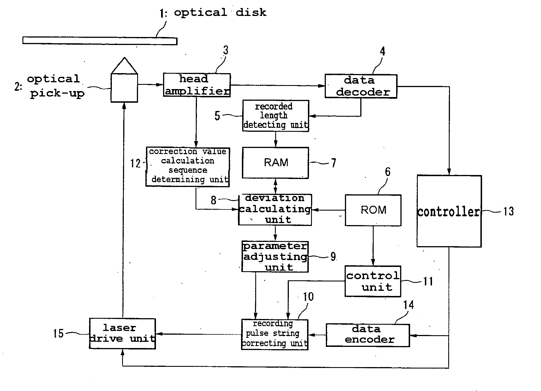
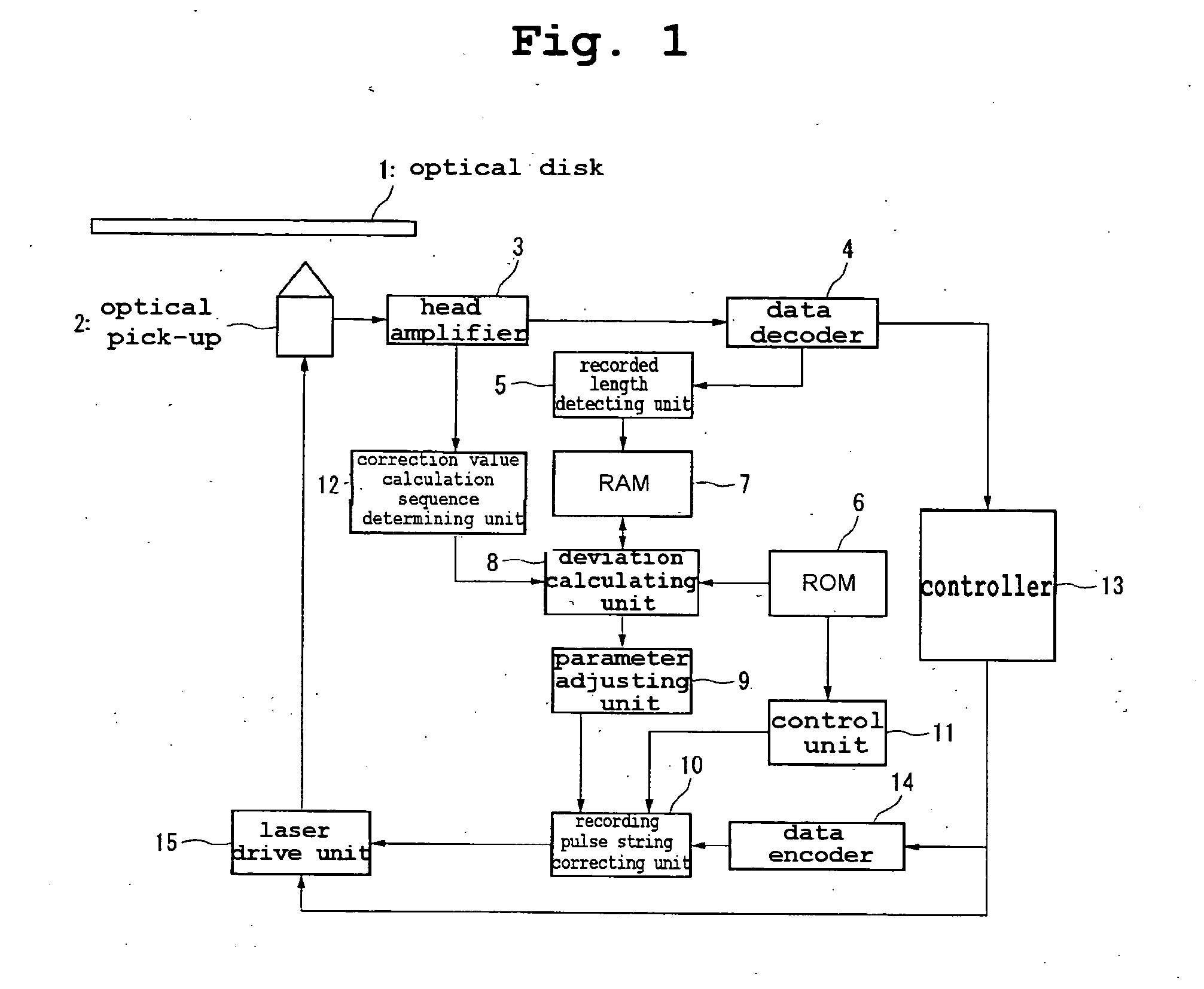
[0046] As shown in FIG. 1, an optical disk device according to an embodiment of the present invention includes an optical disk 1, an optical pick-up 2, a head amplifier 3, a data decoder 4, a recorded length detecting unit 5, Read Only Memory (ROM) 6, Random Access Memory (RAM) 7, a deviation calculating unit 8, a parameter adjusting unit 9, a recording pulse string correcting unit 10, a control unit 11, a correction value calculation sequence determining unit 12, a controller 13, a data encoder 14, and a laser drive unit 15.

[0047] The optical disk 1 is an optical information recording medium in which the recording, reproducing and removing of information can be performed using semiconductor laser. For such optical disks, there are a CD-R, a CD-RW, a DVD-R, a DVD±RW and a DVD-RAM.

[0048] The optical pick-up...


PUM


Abstract

The present invention relates generally to an optical disk device that records and reproduces information on and from an optical recording medium, such as a compact disk or a digital versatile disk. The optical disk device includes a measurement means and a calculation means.

Description

BACKGROUND OF THE INVENTION [0001] 1. Field of the Invention [0002] The present invention relates generally to an optical disk device that records and reproduces information on an optical recording medium, such as a compact disk or a digital versatile disk, and a method of recording optical information. [0003] 2. Description of the Related Art [0004] Recently, as the Internet becomes popularized by the development of information and communication technology, a lot of information has been interchanged through networks. Under such a circumstance, a read only optical device, such as a Compact Disk-Recordable (CD-R), and a recordable optical disk, such as a Compact Disk-Rewritable (CD-RW), attract attention as information recording media. Recently, as a semiconductor laser used as a laser source has a short wavelength, the diameter of a focus tends to be reduced due to a high Numerical Aperture (NA), objective lens having a high NA and a thin substrate is adopted, high capacity optical ...

Claims


Application Information

Patent Timeline
IPC IPC(8): G11B3/00G11B7/0045G11B7/125
CPCG11B7/00456G11B7/0045
Inventor NAKAJO, YUKIHISA
Owner SAMSUNG ELECTRONICS CO LTD
Learn More