Capillary biosensor system and its method of use

a biosensor and capillary technology, applied in the field of capillary biosensors, can solve problems such as obviation of issues, and achieve the effects of improving sensitivity, superior detection strategy, and low detection limi

Inactive Publication Date: 2013-04-11
THE RES FOUND OF STATE UNIV OF NEW YORK
View PDF13 Cites 11 Cited by
  • Summary
  • Abstract
  • Description
  • Claims
  • Application Information

AI Technical Summary

Benefits of technology

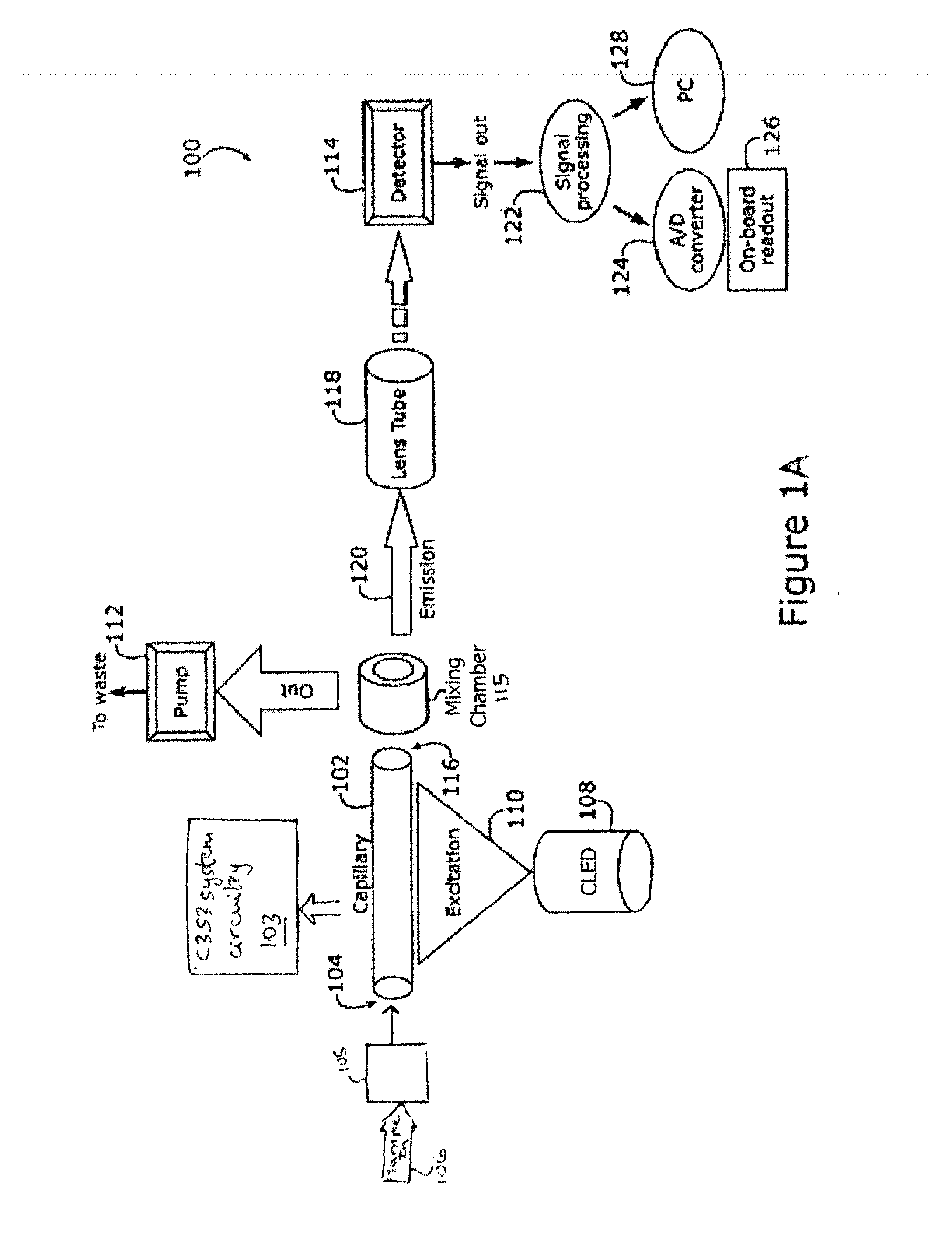
[0012]The ultrasensitive portable capillary biosensor of the present invention utilizes the concept of combining optical transduction with a capillary device resulting in low detection limits and better sensitivity compared to planar array biosensors. In this system, capillaries can support various types of immunoassays ranging from simple sandwich types with a fluorescent tagged antibody attached to the surface, to ELISA assays where fluorescent products are enzymatically produced in solution. In binding assays, the capillary serves as a solid support for immobilizing bioreagents as well as an optical waveguide integrating the signal over an increasing surface area. The present invention utilizes wave guiding properties of the capillary to provide signal enhancement to superior detection strategy when compared to conventional ELISA. This technology is an evolution of an optical biosensor from the original bench-top, laboratory-based design to the current portable system.
[0019]It is an additional object of the present invention to provide a portable biosensor system that may be used by a relatively unskilled operator to provide accurate measurement.

Problems solved by technology

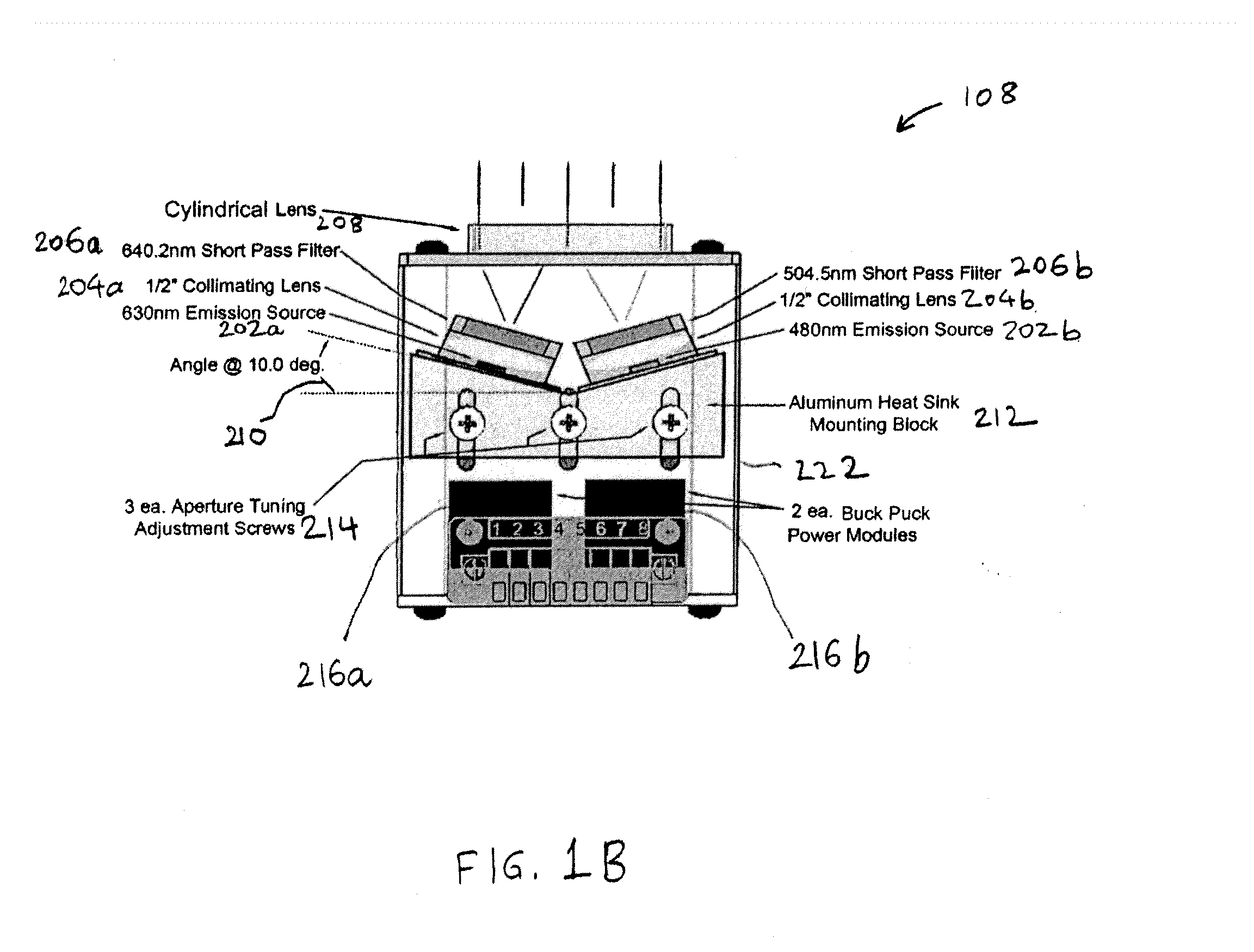
However, this issue is obviated by use of a collimated light source with single or combination of wavelengths the user requires.

Method used


Image

  • Capillary biosensor system and its method of use
  • Capillary biosensor system and its method of use
  • Capillary biosensor system and its method of use

Examples


example 1

Cell Culture, Growth and Survival Application for Mammalian Cell Culture

[0129]The application of the device of the present invention to sustain the culture of IEC-6, A549 and TM-4 has been investigated. It has been found that these cell lines can be successfully cultured inside a 0.1% PDL (Poly-D-lysine) or 1 mg PDL / 10 mL sterile water coated capillary (ID=1.0 mm, OD=0.78 mm, length=38 mm). The optimum number of each cell lines in the capillary varies (typically around 7000 cells / capillary). It has also been found that A549 can survive within the capillary for at least 14 days. These results had been verified using Trypan Blue assay. It was observed that different concentrations of PDL have no direct effect on how well the cells can survive inside the capillary 102. The cell-lines used here are the adhesion type, which require attachment to a substrate in order to seed, survive, spread, and grow. Cells typically do not attach to substrates whose surfaces are uncharged or hydrophobic...

example 2

Polymer Coating Procedures

[0130]The interior of the capillary tube 102 of the present invention is coated in the following exemplary fashion:

[0131]1. Borosilicate capillary glass tubing (ID=0.78 mm, OD=1.00 mm, Length=39 mm) was autoclaved at 134° C. for 35 minutes.

[0132]2. 1 mg Poly-D-lysine hydrobromide purchased from Sigma-Aldrich was dissolved in 10 mL sterile tissue culture grade water.

[0133]3. The dissolved solution was injected into sterile capillary glass tubing by using BD Ultra-Fine Insulin Syringe (capacity: 0.5 ml, length: 12.7 mm, gauge: 30 G). The capillary was rocked gently to ensure even coating inside the capillary.

[0134]4. Capillary 102 was thoroughly rinsed after 5 minutes using sterile tissue culture grade water. The liquid residues were removed by aspiration.

[0135]5. Capillary 102 was allowed to dry overnight inside a Laminar Flow hood (Ductless PCR workstation) before introducing cells and medium.

example 3

Analysis of Cells

[0136]Capillaries are coated by adding 10 mL of sterile tissue culture grade water to 1 mg of poly-D-Lysine at pH 7.32. The resulting solution is introduced to sterile glass capillaries via ultrafine insulin syringe. The capillaries are rocked gently to promote even coating and drying. Then, the inner surfaces of the capillaries are thoroughly rinsed with sterile tissue culture grade water to remove any residue. The coated capillaries are dried overnight before introducing cells. Following successful polymer coating, the capillaries are seeded with mammalian cells to allow growth. Typically, a few cells (5-10) per capillary is equivalent to a plating density of 5000-7,000 cells per standard 96 well (0.32 cm2) tissue culture plate. Capillaries are kept within the C3S3 compartment under controlled conditions (37° C., 5% CO2) and the culture media are changed periodically until the cells reach confluence. Cell viability is then determined using any cell-permeable compo...


PUM

PropertyMeasurementUnit
spectral widthaaaaaaaaaa
wavelengthsaaaaaaaaaa

Abstract

A portable biosensor system includes at least one capillary tube extending longitudinally along a major axis between a proximal inlet end and a distal end. The at least one capillary tube has an interior surface coated with a capture material and forms a waveguide. At least one collimated light emitting diode is disposed proximate and perpendicular to the major axis of the at least one capillary tube and is positioned relative to the at least one capillary tube so that energy enters the at least one capillary tube from its exterior along the entire length of the at least one capillary tube to project a line of energy along substantially the entire longitudinal extent of the at least one capillary tube. A photosensor is disposed proximate the distal end of the at least one capillary tube for receiving emissive radiation therefrom. The photosensor generates an output voltage (or, optical output) representative of the emissive radiation, and a means for measuring the output voltage is provided. Also disclosed is a method of detecting target molecules in a sample using the biosensor of the present invention.

Description

[0001]This application claims the benefit of U.S. Provisional Patent Application Ser. No. 61 / 325,663, filed Apr. 19, 2010, which is hereby incorporated by reference in its entirety.[0002]This invention was made with government support under grant number RD834091010 awarded by United States Environmental Protection Agency (USEPA). The government has certain rights in this invention.FIELD OF THE INVENTION[0003]The present invention relates to a capillary biosensor and its method of use.BACKGROUND OF THE INVENTION[0004]Biosensors are devices that typically use biological molecules to detect other biological molecules or chemical substances. Detection of food-borne pathogens, biochemical agents, environmental toxins or early cancer biomarkers, requires elaborate time-consuming culturing techniques that must be completed in a microbiology laboratory. Cell-based biosensors (CBBs) can simplify many of these applications and provide better approach towards early detection with improved prog...

Claims


Application Information

Patent Timeline
Patent Type & Authority Applications(United States)
IPC IPC(8): G01N33/566G01N33/53
CPCG01N21/6428G01N21/7703G01N2021/0346G01N33/566G01N2201/0221G01N33/5302G01N2021/7786
Inventor SADIK, OMOWUNMI A.WANG, QIONGBLYTHE, SR., PAUL A.
Owner THE RES FOUND OF STATE UNIV OF NEW YORK
Why Eureka
Try Eureka