Fuel supply pump

a technology of fuel supply pump and pump body, which is applied in the direction of liquid fuel engine, machine/engine, positive displacement liquid engine, etc., can solve the problems of insufficient degree of pressurization and fuel flow rate to allow higher power of diesel engine, complicated assembly work, and insufficient degree of pressurization and fuel flow rate, so as to achieve a large flow rate and increase fuel efficiency. , the effect of increasing the power

Inactive Publication Date: 2005-05-12
DIESEL KIKI CO LTD
View PDF8 Cites 27 Cited by
  • Summary
  • Abstract
  • Description
  • Claims
  • Application Information

AI Technical Summary

Benefits of technology

[0010] That is, as constructed above, the inner peripheral surface of the pump housing does not require a projection for supporting the upper end of the return spring. Thus, no obstacle is provided on the inner peripheral surface of the pump housing has, so that the respective structural components such as the tappet structure body, the plunger barrel, and the plunger can be temporarily preassembled and inserted into the cylindrical space of the housing from the upper portion of the pump housing. In addition, no floor plug for inserting the tappet structure body is required. Consequently, the fuel supply pump simple in construction and easy to produce can be provided.
[0024] Using such an accumulator fuel injection device, the pressurization of the fuel having a large flow rate can be easily carried out. Therefore, the accumulator fuel injection device attains a further increase in fuel efficient, so that a diesel engine will have a higher power and an increase in fuel consumption, while attaining a reduction in particulate matters, and so on.

Problems solved by technology

Consequently, in the conventional fuel supply pump, there are problems in that the assembly work is complicated and the production cost is not easily reduced.
However, the degree of pressurization and the flow rate of fuel are still insufficient to allow higher power of the diesel engine.

Method used


Image

  • Fuel supply pump
  • Fuel supply pump
  • Fuel supply pump

Examples


Embodiment Construction

[0041] Hereinafter, the fuel supply pump will be described concretely with proper references to the drawings.

1. Basic Configuration of Fuel Supply Pump

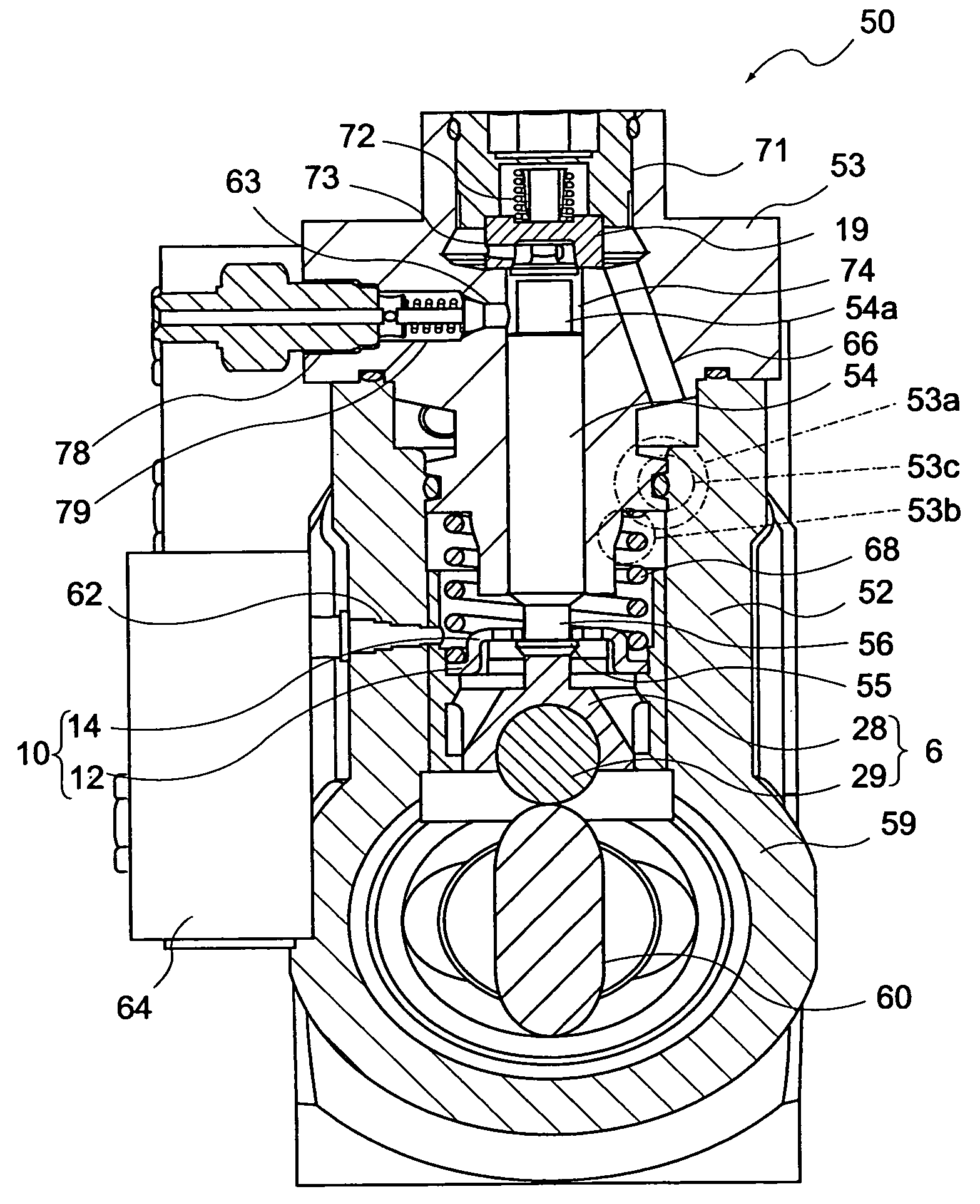
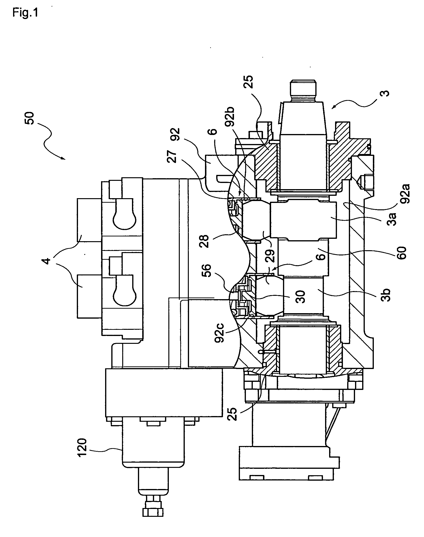
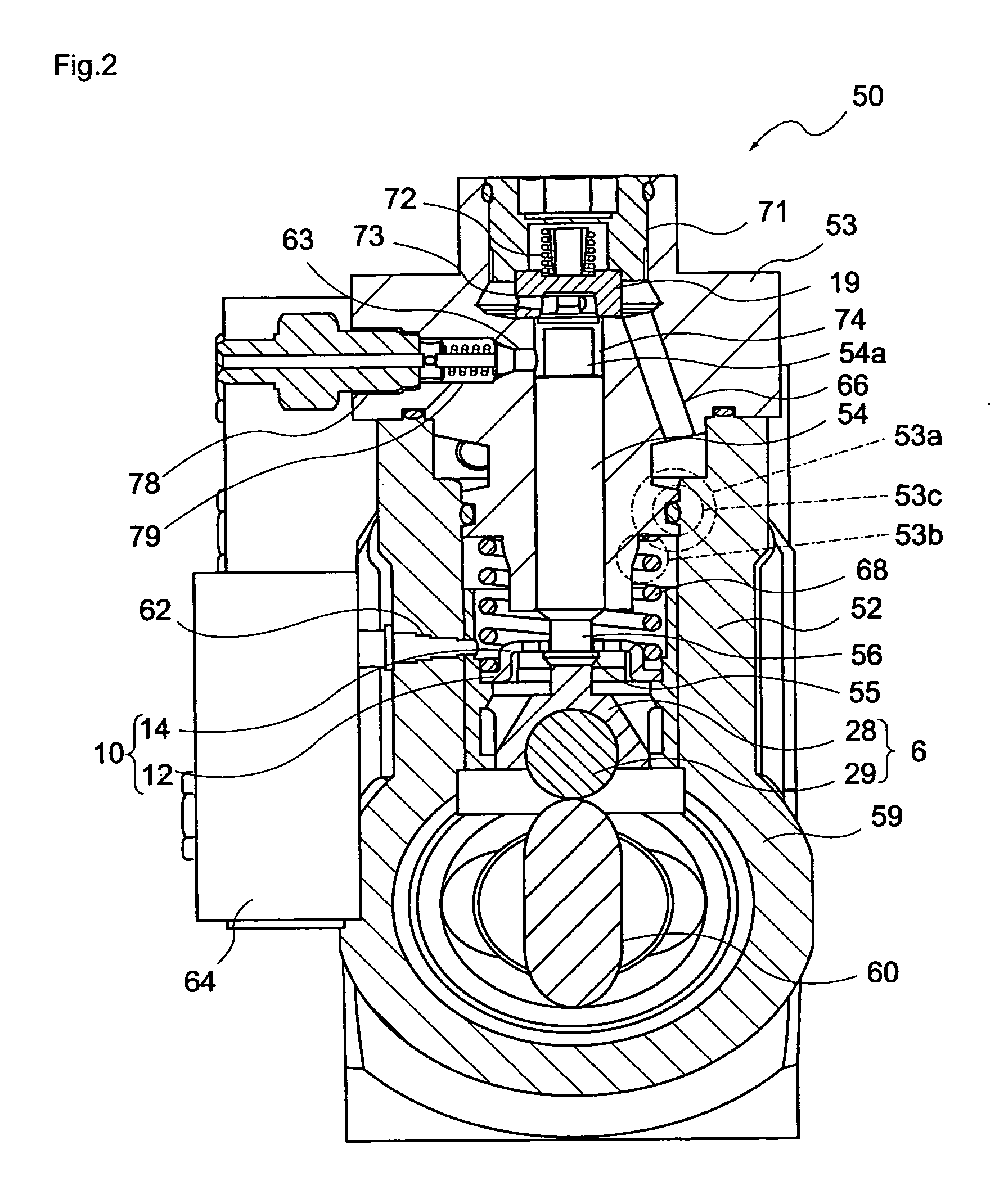
[0042] As shown in FIG. 1 and FIG. 2, the present embodiment is a fuel supply pump 50 comprising: a pump housing 52 having a cylindrical space opened from end to end in the vertical direction; a plunger barrel 53 installed in the upper opening portion of the pump housing 52; a plunger 54 for pressurizing fuel, which is installed in the plunger barrel 53 and the cylindrical space of the pump housing 52 so as to be allowed to move up and down; a cam 60 installed in rotation way below the plunger 54 and integrated with a cam shaft 3 inserted into the pump housing 52; a tappet structure body 6 installed between the cam 60 and the plunger 54 and provided for transmitting a upward or downward movement of the cam 60 caused by the rotation of the cam shaft to the plunger 54; and a return spring 68 for setting lowering force to the plunger ...


PUM


Abstract

A fuel supply pump, which is simple in construction and easy to produce and is capable of efficiently pressurizing a high flow rate of fuel, is provided. The fuel supply pump (50) includes a housing (52), a plunger barrel (53), a plunger (54) for pressurizing fuel, which is installed in the plunger barrel (53) so as to be allowed to move up and down, a cam (60) installed in rotation way below the plunger (54), a tappet structure body (6) installed between the cam (60) and the plunger (54) to transmitting the turning force, serving as a lifting force, from the cam shaft (3) to the plunger (54), a tappet structure body (6) installed between the cam (60) and the plunger (54) and provided for transmitting a upward or downward movement of the cam (60) caused by the rotation of the camshaft (3) to the plunger (54); and a return spring (68) for setting lowering force to the plunger (54), which is installed between the tappet structure body (6) and the plunger barrel (53).

Description

TECHNICAL FIELD [0001] The present invention relates to a fuel supply pump. Particularly, the present invention relates to a fuel supply pump suitable for an accumulator fuel injection device with a pressure-amplifying piston (APCRS: Amplified Piston Common Rail System) that requires a high flow rate of pressurized fuel. BACKGROUNDS [0002] A conventional fuel supply pump 250 has been constructed as shown in FIG. 16. The conventional fuel supply pump 250 comprises: a pump housing 252 having a cylindrical space opened from end to end in the vertical direction; a plunger barrel 253 installed in the upper opening portion of the pump housing 252; a plunger 254 for pressurizing fuel, which is installed in the plunger barrel 253 and the cylindrical space of the pump housing 252 so as to be allowed to move up and down; a cam 260 installed in a rotation way below the plunger 254 and integrated with a cam shaft 3 (not shown) inserted into the pump housing 252 in the longitudinal direction; a ...

Claims


Application Information

Patent Timeline
Patent Type & Authority Applications(United States)
IPC IPC(8): F02M59/10F02M59/44F04B1/04F04B53/16
CPCF02M59/102F02M59/442F04B53/162F04B1/0426F04B1/0439F04B1/0421
Inventor AOKI, NOBUOKUBOTA, KAZUYAARAKI, TAKESHI
Owner DIESEL KIKI CO LTD
Why Eureka
Try Eureka