Energy savings device and method for a resistive and/or an inductive load and/or a capacitive load

a technology of inductive load and energy saving device, which is applied in the direction of instruments, light sources, electrical equipment, etc., can solve the problems of affecting the efficiency of power-to-light output, and increasing air conditioning costs, so as to achieve energy saving

Inactive Publication Date: 2005-05-19
ASTRAL COMM
View PDF16 Cites 73 Cited by
  • Summary
  • Abstract
  • Description
  • Claims
  • Application Information

AI Technical Summary

Benefits of technology

[0015] According to yet another aspect of the invention, there is provided a computer program product for providing energy savings for an inductive, resistive or capacitive load that is powered by an input AC voltage waveform. The computer program product includes first computer code configured to set a desired power operating level for the load. The computer program product also includes second computer code configured to receive a setting signal output from the first computer code that is indicative of the desired power operating level for the load, the second computer code further configured to determine a phase delay to be provided to an output AC voltage waveform that is to be provided to the load, and to output a control signal as a result thereof. The computer program product further includes third computer code configured to synchronize to a Safety Ground line, to thereby provide a synchronization signal that is used in construction of the control signal by the second computer code.

Problems solved by technology

Lighting levels that are higher than necessary not only result in a higher energy costs associated with the lighting, but also can increase air conditioning costs due to the excess heat provided by the lighting fixtures.
The resulting power-to-light output efficiency is hampered by this additional manipulation.
This type requires an expensive fixture replacement and rewiring to the wall switch.
Simplistic phase control devices will not provide satisfactory results when controlling a magnetic ballast fluorescent fixture.
Since connectivity to the neutral line 104 is not always available at a light switch box, conventional fluorescent controllers may require expensive re-wiring to be installed.
The problem with using such a conventional dimmer circuit for a fluorescent lighting fixture is that the conventional dimmer circuit cannot modulate reactive loads.
Reactive loads react with the controller, thereby producing oscillations that then cause surges of voltage and current, which are both unpredictable and uncontrollable.
Such flickering is visually (and also audibly) discomforting, and may even be unhealthful to people who are near the flickering fluorescent light (for example, it may cause headaches due to having to view the undesirable light flickering).
As explained earlier, a controller such as the one shown in FIG. 1A can be used to control a fluorescent light without causing significant flickering, but such a controller requires fairly substantial installation costs, since they cannot be installed at a light switch box (where a neutral line is not typically provided), but rather have to be installed very close to the ballast (e.g., in the ceiling of a room, where a neutral line is provided).
However, due to the analog structure and the various components described in the Talbott et al. device, such a device is very difficult to manufacture, and also such a device is very difficult to manufacture in a small size.
Thus, it is not feasible to install such a device in a light switch box, given the bulkiness as well as the transformer configuration of the Talbott et al. device.

Method used


Image

  • Energy savings device and method for a resistive and/or an inductive load and/or a capacitive load
  • Energy savings device and method for a resistive and/or an inductive load and/or a capacitive load
  • Energy savings device and method for a resistive and/or an inductive load and/or a capacitive load

Examples


first embodiment

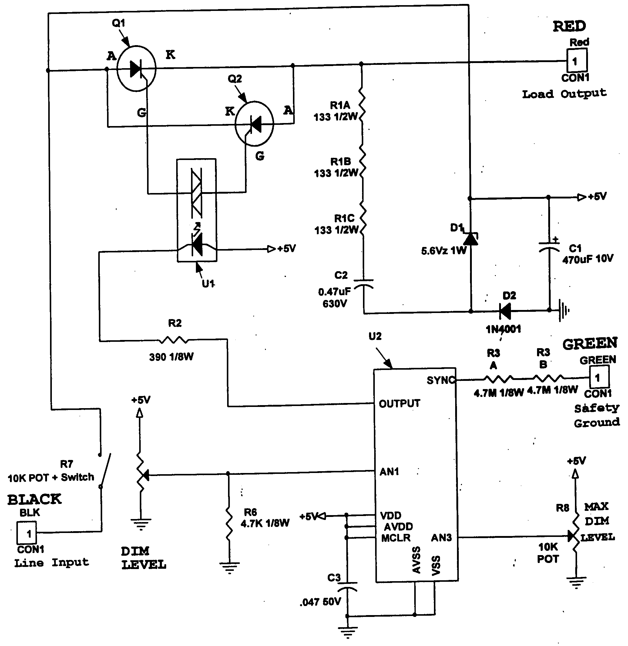
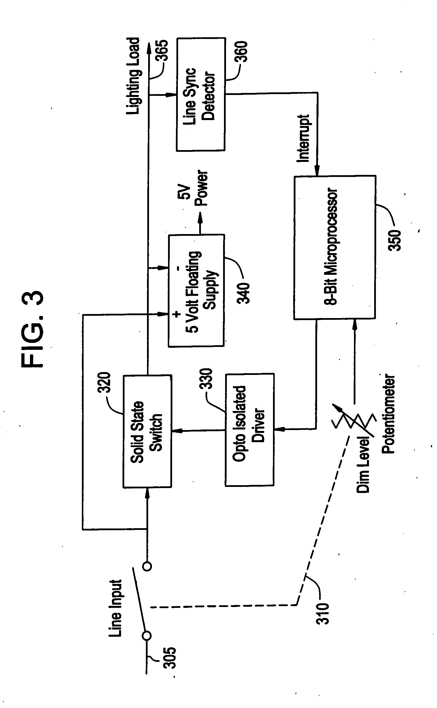
[0039] The UCD includes a “push” On / Off switch and potentiometer unit 310 that is coupled to a line input (AC input voltage) 305, a solid state switch unit 320, a driver 330 for driving the solid state switch unit 320, a power supply 340, a microprocessor 350, and a line synchronization detector 360. The solid state switch unit 320 is provided between the line input 305 and the load 365. The switch and potentiometer unit 310 includes a “push” On / Off switch SW 1 and a potentiometer POT. The line synchronization detector 360 provides an interrupt signal to the microprocessor 350, which corresponds to “rising” zero crossing of a load current waveform, to be explained in more detail below.

[0040] The UCD is a two wire dimmer unit, and can be utilized to control standard magnetic fluorescent fixtures. The UCD may also be used to control other resistive, inductive or capacitive (e.g., standard electronic fluorescent fixtures) loads. The UCD functions similar to incandescent dimmers, but i...

second embodiment

[0159] As shown in FIG. 7, an ambient light sensor unit 710 of the second embodiment provides the capability to adjust the dimming level for constant level illumination during day / night ambient illumination variances. Referring also to FIG. 8, the ambient light sensor unit 710 includes a photo-resistor R19 with amplifier 720, which provides a stable indication of the total ambient illumination via a signal AMBLITE provided to port 1 of the microprocessor U2. The microprocessor U2 adjusts the dimming level to maintain this total ambient illumination level. For example, during a cloudy day, if the clouds break during the afternoon and thus the light through windows of an office increases, this results in an increase in the illumination level picked up by the ambient light sensor unit 710. Accordingly, the microprocessor U2 will adjust the load current waveform to provide a slightly dimmer signal than what was previously provided (during the cloudy period), so as to maintain a stable a...

seventh embodiment

[0167] The seventh embodiment includes a conduction angle phase switching circuit connected in parallel with a reactive load, an AC power source for switching power across the load, and a line switching circuit for enabling the application of AC power to the load through the phase switching circuit.

[0168] In the seventh embodiment, an ambient light sensor 910 is provided for generating a light control signal indicative of the amount of ambient light present in a particular location. Coupled to the light sensing circuit is a phase angle conduction control circuit, which generates and applies to a control terminal of the phase switching circuit a phase control signal to control the phase angle conduction time of the phase switching circuit, based on the amount of ambient light measured by the light sensing circuit, in order to maintain a substantially constant lighting level. In FIG. 9, the microprocessor U3 functions as the phase angle conduction control circuit.

[0169] Integrated wi...


PUM


Abstract

An energy savings device for an inductive, a resistive or a capacitive load, such as a fluorescent light fixture having a magnetic ballast or an electronic ballast, which is powered by an AC voltage waveform. The energy savings device includes a setting unit for setting a desired power operating level for the load. The energy savings device also includes a processor configured to receive a signal from the setting unit indicative of the desired power operating level for the load, to determine a phase delay to be provided to an output AC voltage waveform that is to be provided to the load, and to output a control signal as a result thereof. The energy savings device further includes an active element provided between a line that provides the input AC voltage waveform and the load, the active element receiving the control signal and turning off and on at predetermined times in accordance with the control signal, so as to create the output AC voltage waveform from the AC voltage waveform. The processor includes a synchronization circuit that synchronizes to the Green Safety ground line.

Description

RELATED APPLICATIONS [0001] This application is a continuation-in-part of U.S. patent application Ser. No. 10 / 454,840, filed Jun. 5, 2003, which is itself a continuation-in-part of U.S. patent application Ser. No. 10 / 205,031, filed Jul. 26, 2002 (which matured into U.S. Pat. No. 6,724,157, issued Apr. 20, 2004), whereby this application also claims priority to provisional patent application 60 / 336,222, filed Nov. 14, 2001.BACKGROUND OF THE INVENTION [0002] A. Field of the Invention [0003] The invention relates to an energy savings device or method that can be applied to a resistive, an inductive, or a capacitive load regardless of the respective impedance or inductance or capacitance of the load. More particularly, the invention relates to a load dimming device that is mounted in series with a resistive, an inductive or a capacitive load and that has access for power and operation to one side of an electrical line supplied to the load. A fluorescent light fixture or a motor for a fa...

Claims


Application Information

Patent Timeline
Patent Type & Authority Applications(United States)
IPC IPC(8): H05B39/08H05B41/392
CPCH05B37/0227H05B39/08Y02B20/40H05B41/3924H05B41/3922H05B47/14
Inventor KAZANOV, ANATOLY L.PAIGE, ANTHONYHALL, MARK
Owner ASTRAL COMM
Why Eureka
Try Eureka