Power converter system

a power converter and power technology, applied in the direction of motor/generator/converter stopper, electric generator control, dynamo-electric converter control, etc., can solve the problems of low cost of photovoltaic arrays, inability to control the power supply of power supply transformers, etc., to achieve the effect of preventing current flow

Active Publication Date: 2005-05-19
RHOMBUS ENERGY SOLUTIONS
View PDF18 Cites 184 Cited by
  • Summary
  • Abstract
  • Description
  • Claims
  • Application Information

AI Technical Summary

Benefits of technology

[0016] In another aspect, a method for optimizing integration of a direct current generating device with a three phase power grid comprises providing a power conversion system comprising first and second converters each being capable of selective three phase passive and active rectification/inversion; connecting a direct current generating device to two grounded phases of the first converter and one remaining phase of the first c...

Problems solved by technology

For example, in photovoltaic applications the cost of photovoltaic arrays is still relatively high, and the physical area occupied by photovoltaic arrays may be undesirably large, particular where real estate is at a premium.
It is anticipated that the cost of photovoltaic arrays, for example, will decline.
Thus, the relative cost of the power converter itself will become a more significant component of the entire system cost.
Currently, the cost of power converters themselves is unnecessarily high due to the lack of generality, and high specificity of power converter designs for different applications.
This lack of generality in power converter designs (i.e., highly use-specific engineering) prevents significant cost savings which may be derived from production of a generalized design which is applicable to a multiplicity of purposes.
The device disclosed by ...

Method used


Image

  • Power converter system
  • Power converter system
  • Power converter system

Examples


Embodiment Construction

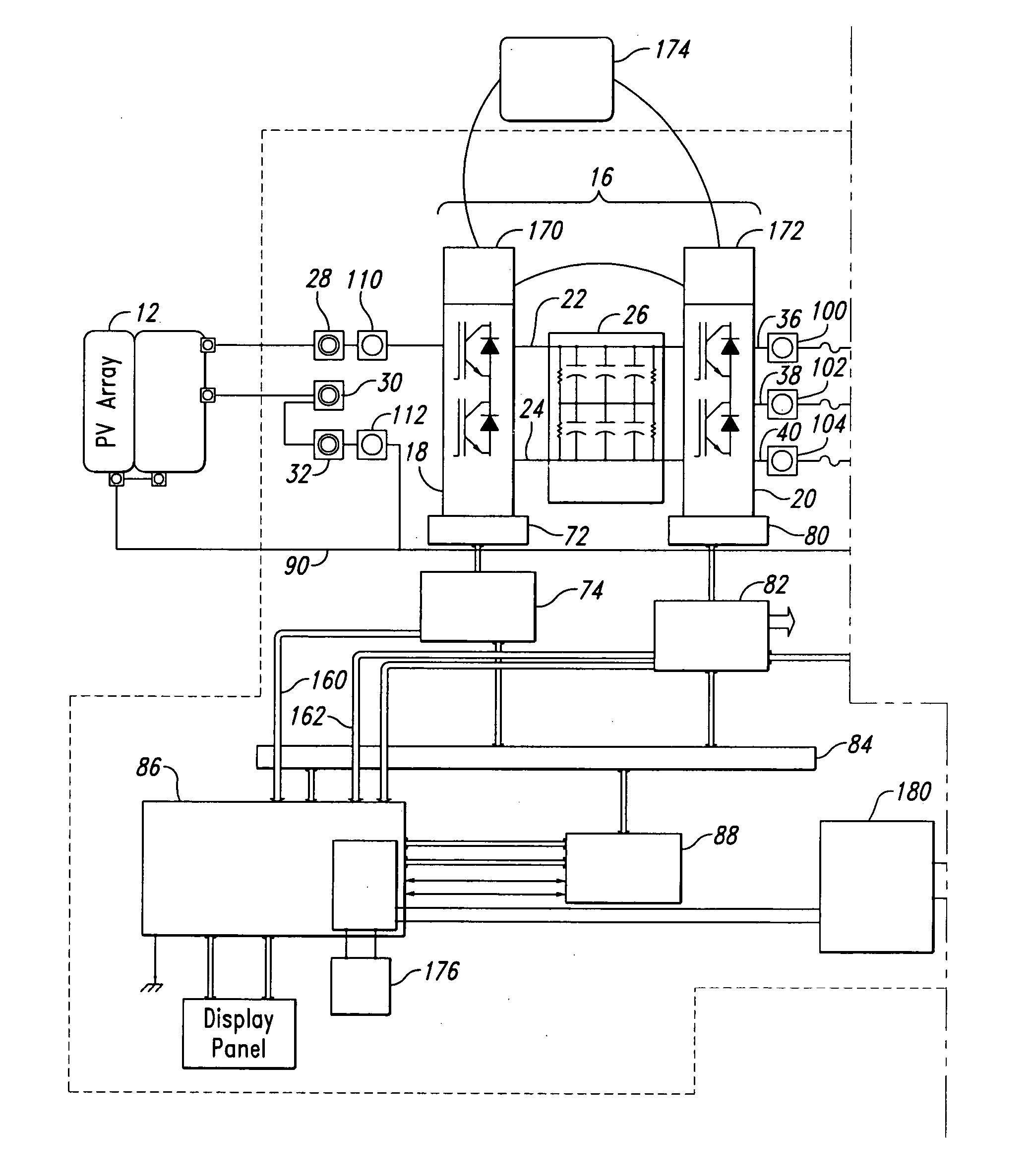
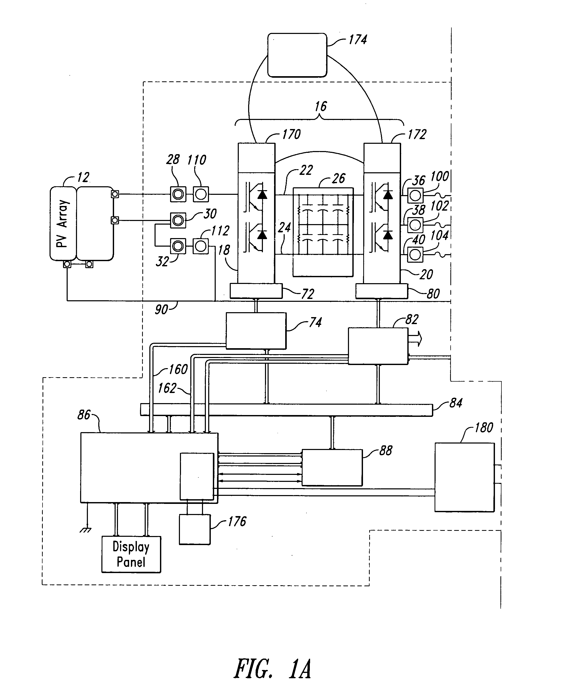
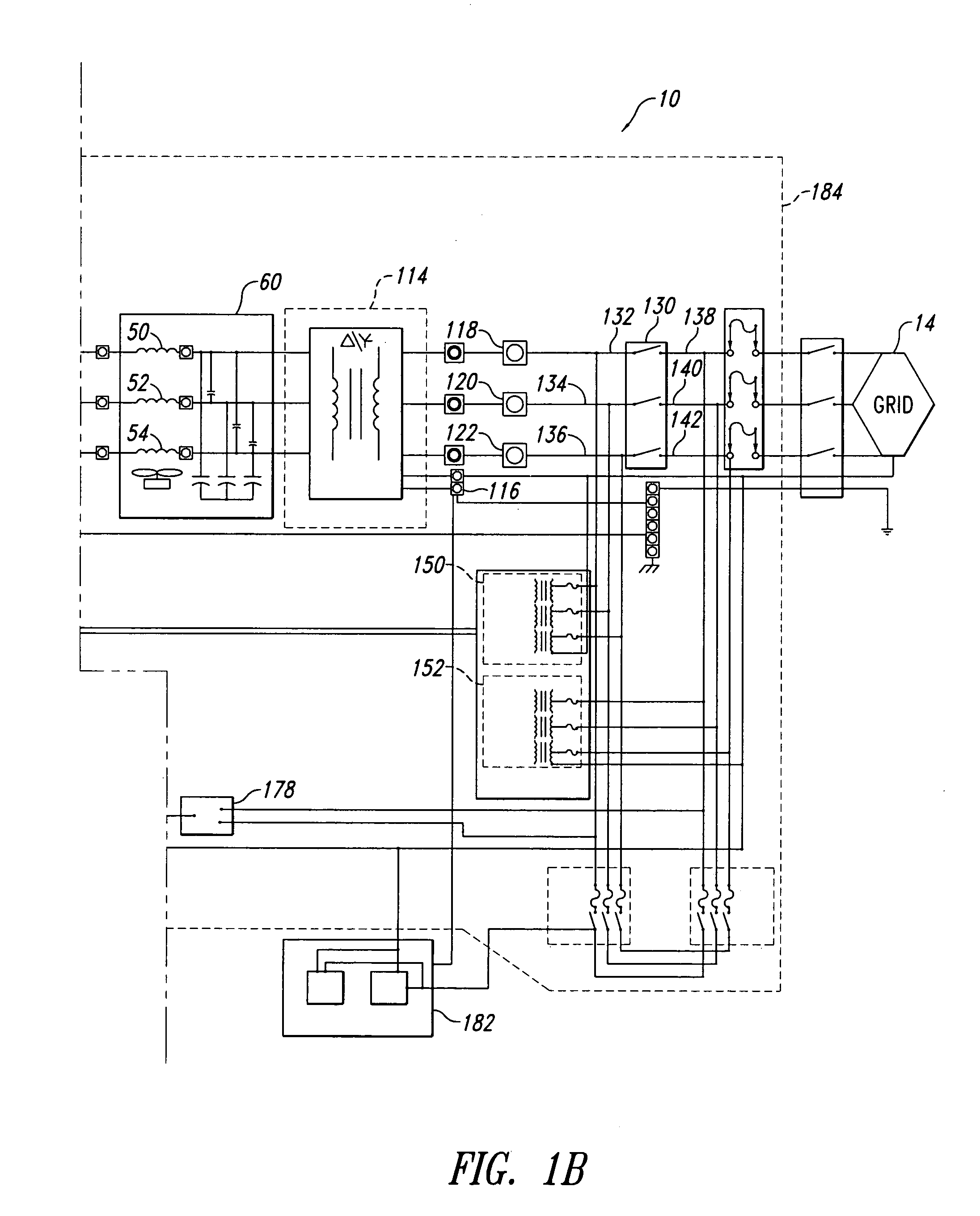
[0019] A power converter system employing the principles of the present disclosure is generally indicated at reference numeral 10 in FIG. 1 wherein reference numerals herein correspond to like-numbered elements in the various figures. In the following discussion, certain specific details are set forth in order to provide a thorough understanding of various embodiments of the invention. However, one of ordinary skill in the art will understand that the invention may be practiced without these details. In other instances, well-known structures associated with power converter systems have not been shown or described in order to avoid unnecessarily obscuring descriptions of embodiments of the invention, unless the context requires. Otherwise, throughout the specification and claims which follow, the word “comprise” and variations thereof, such as “comprises” and “comprising,” are to be construed in an open and inclusive sense, that is as “including, but not limited to.” Reference throug...


PUM


Abstract

A power converter system advantageously employs a modular, bi-directionally symmetrical power converter assembly in a readily customizable configuration to interconnect a direct current power source to a three-phase alternating power grid. Connections external to the power converter assembly are selected to optimize the power converter system for a specific application, such as interconnecting a photovoltaic array to the three-phase electrical power grid. The electrical interconnections of various elements including isolation transformers, voltage sensors, and control switches are optimized to improve efficiency and reliability.

Description

BACKGROUND OF THE INVENTION [0001] 1. Field of the Invention [0002] The present disclosure relates to electric power converter systems. More specifically, the disclosure relates to power converter systems suitable for interconnecting direct current output power sources (e.g., photovoltaic arrays) to a three-phase alternating current power grid. [0003] 2. Description of the Related Art [0004] Electric power converter systems are used to transform and / or condition electrical power in a variety of applications. For example, electrical power converter systems may transform AC power from a power grid to a form suitable for a standalone application (e.g., powering an electric motor, lights, electric heater, household or commercial equipment, telecommunications equipment, computing equipment, uninterruptible power supply (hereinafter occasionally “UPS”)). Also for example, electrical power converter systems may transform power from a standalone power source such as an array of photovoltaic...

Claims


Application Information

Patent Timeline
IPC IPC(8): H02J3/38H02M5/458H02M7/797
CPCH02M5/4585H02M7/797H02J3/387Y02E10/563H02J3/383Y02B10/14H02J2300/30H02J2300/24H02J3/381Y02B10/10Y02E10/56
Inventor DENG, DUOBHAVARAJU, VIJAY
Owner RHOMBUS ENERGY SOLUTIONS
Why Eureka
Try Eureka