CO2 waveguide laser with beryllium oxide waveguides

Active Publication Date: 2005-05-19
COHERENT INC
View PDF11 Cites 28 Cited by
  • Summary
  • Abstract
  • Description
  • Claims
  • Application Information

AI Technical Summary

Problems solved by technology

Unfortunately, the average power output for a pulsed waveguide CO2 laser operating at a wavelength

Method used


Image

  • CO2 waveguide laser with beryllium oxide waveguides
  • CO2 waveguide laser with beryllium oxide waveguides
  • CO2 waveguide laser with beryllium oxide waveguides

Examples


Embodiment Construction

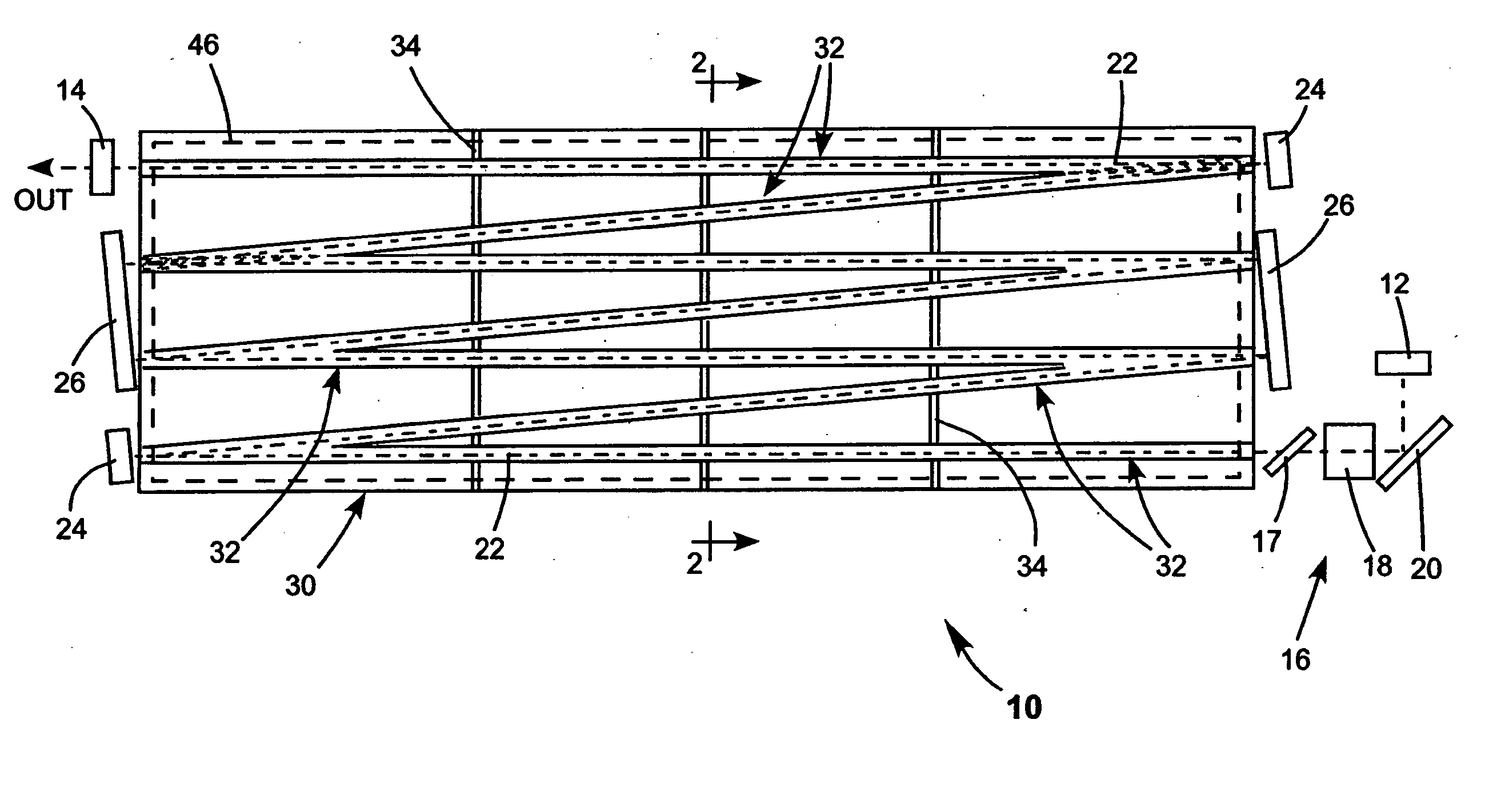
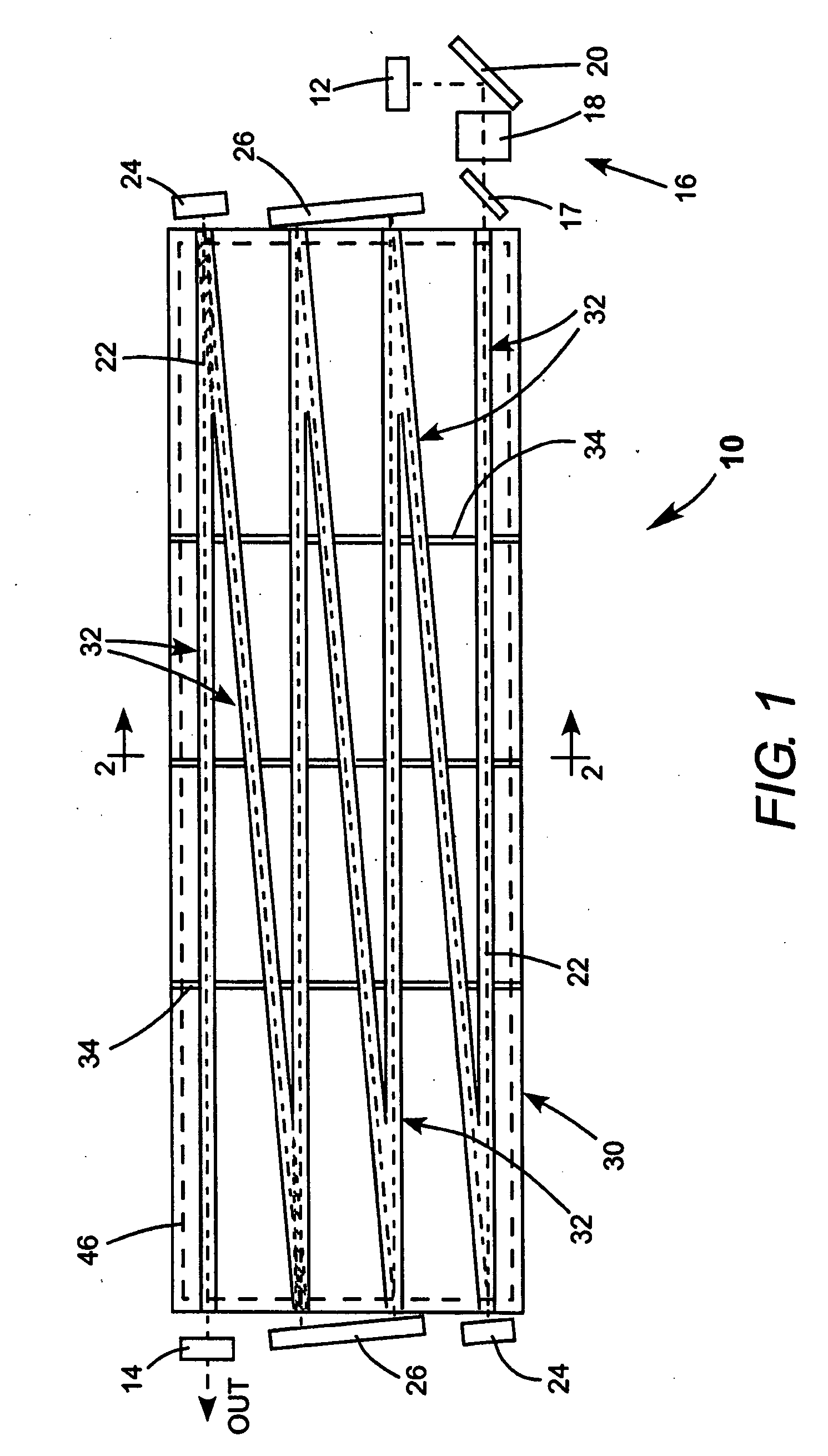
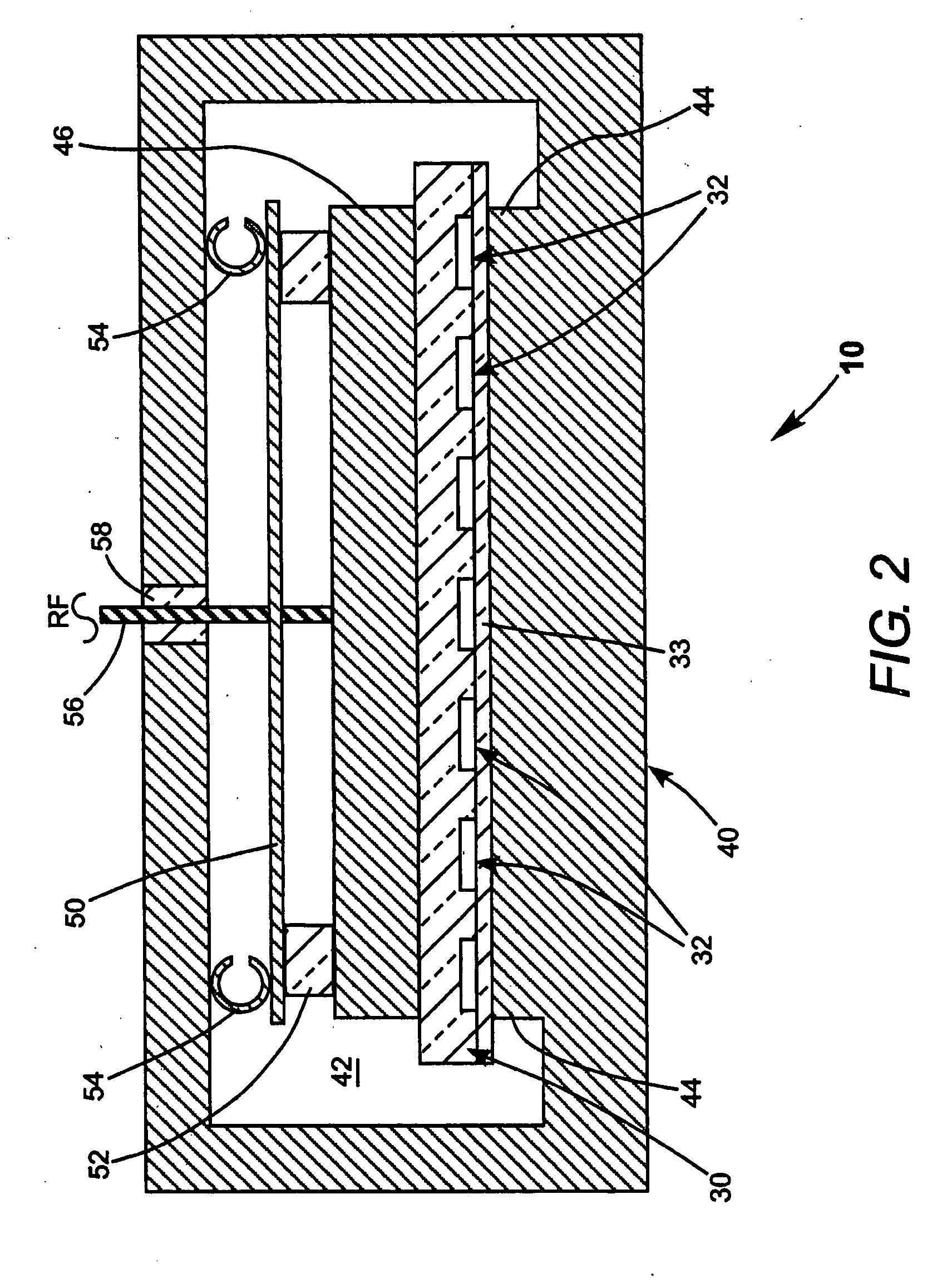
[0013] Turning now to the drawings wherein like features are designated by like reference numerals, FIG. 1 and FIG. 2 depict one preferred embodiment 10 of a Q-switched, pulsed CO2 laser in accordance with the present invention. The laser is arranged to deliver laser radiation at a selected wavelength in a wavelength range between about 9.2 μm and 9.7 μm. Laser 10 includes a laser resonator terminated by a maximally reflecting mirror 12 and a partially reflecting mirror 14. Mirror 14 serves an output coupling (OC) mirror. By way of example, mirror 12 preferably has a reflectivity greater than 99%, and mirror 14 preferably has a reflectivity between about 20% and 40%. Laser 10 includes a Q-switch arrangement 16 for causing the laser to operate as a pulsed laser. Q-switch arrangement 16, here, includes a thin film polarizer (TFP) 17, a cadmium telluride (CdTe) electro-optical switch 18 and a reflective phase retarder (RPR) 20. Details of operation this and other possible Q-switch arra...


PUM


Abstract

A pulsed, Q-switched, waveguide CO2 laser includes a plurality of waveguide channels formed in a block of a beryllium oxide ceramic material and is operated at a wavelength between about 9.2 and 9.7 micrometers. The laser has an output power up to 55% greater than that of a similarly configured laser, operated at the same wavelength and pulse conditions, but wherein the waveguide channels are formed in a block of an alumina ceramic material.

Description

TECHNICAL FIELD OF THE INVENTION [0001] The present invention relates generally to carbon dioxide (CO2) lasers. The invention relates in particular to pulsed lasers emitting radiation at wavelengths between about 9.2 micrometers (μm) and about 9.7 μm. DISCUSSION OF BACKGROUND ART [0002] Waveguide CO2 lasers are lasers in which lasing modes are constrained in zigzag arrangement of waveguide channels machined in a ceramic slab. Aluminum oxide (alumina—Al2O3) is the most commonly used ceramic material for the waveguide slab, for reasons including ease of machinability and a low cost relative to other machinable ceramics. The aluminum oxide ceramic slab is bounded by electrodes for exciting an RF discharge in a lasing gas in the waveguide channels. The RF discharge energizes the lasing gas for providing optical gain. A plurality of mirrors provides a folded laser resonator having a resonator axis extending through the zigzag arrangement of waveguides. Waveguide CO2 lasers can be arrange...

Claims


Application Information

Patent Timeline
IPC IPC(8): H01S3/03H01S3/07H01S3/223
CPCH01S3/0305H01S3/2232H01S3/076H01S3/0315
Inventor SEGUIN, VERNONNEWMAN, LEONKENNEDY, JOHN
Owner COHERENT INC
Why Eureka
Try Eureka