Cable-terminating modular plug

a technology of modular plugs and plugs, which is applied in the direction of coupling device details, coupling device connections, contact members penetrating/cutting insulation/cable strands, etc., can solve the problems communication problems in networks, distortion and displacement of wire twisted signal pairs, etc., to prevent relative movement between the cable and the plug. , the effect of enhancing crimping

Inactive Publication Date: 2005-05-19
BEL FUSE
View PDF0 Cites 51 Cited by
  • Summary
  • Abstract
  • Description
  • Claims
  • Application Information

AI Technical Summary

Benefits of technology

[0011] In order to achieve these objects and others, a modular plug for terminating a cable having twisted signal pairs of wires includes a plug housing having contact blade-receiving slots at a front end and defining a longitudinally extending cavity opening at a rear end, a strain relief member defining a channel for receiving the cable, and a wire aligner interposed between the strain relief member and the housing and arranged at least partially in the cavity. The wire aligner has a dual function in the invention in that it both aligns the wires of the cable into specific positions relative to the slots in the plug housing and also crimps or pinches the cable in the channel of the strain relief member. Since the cable is not pinched in the plug housing, and distortion and displacement of the twisted signal pairs of wires of the cable within the plug housing does not occur. Accordingly, variations in NEXT are reduced.
[0012] Another advantage obtained by the use of a wire aligner which provides both wire-alignment and cable-crimping functions is that it eliminates the need for a separate cable crimping member as in some prior art constructions, e.g., the crimping ring in the '949 patent described above.
[0013] In one embodiment, the crimping function of the wire aligner is provided by integral retention fingers which extend rearwardly from the wire aligner into the channel and are inclined inward toward a center of the channel. The inclined retention fingers abut and are deformed by a tapering, conical surface of the channel to thereby exert a compressive force against the cable when received in the channel. To enhance the crimping provided by the retention fingers, serrations may be formed on an inner surface at a rearward end of the retention fingers so that the retention fingers frictionally engage the cable. This prevents relative movement between the cable and the wire aligner. Since the wire aligner is attached to the strain relief member and the plug housing, relative movement between the cable and the plug is prevented.

Problems solved by technology

When data is transmitted via alternating current in a typical telecommunication application at such high frequencies, each individual wire and each signal pair creates an electromagnetic field that can interfere with signals on adjacent wires and adjacent signal pairs.
This undesirable coupling of electromagnetic energy between adjacent wire pairs is commonly referred to as crosstalk and causes communication problems in networks.
Controlling NEXT involves not only a reduction in NEXT but also a reduction in variations in NEXT between signal pairs of the wires because technical specifications limit acceptable variations in NEXT.
However, it remains a problem to provide strain relief for the cable while avoiding causing NEXT and variations in NEXT between twisted signal pairs because the strain relief usually causes pinching and deformation of the cable within the plug housing which results in distortion and displacement of the twisted signal pairs of wires.

Method used


Image

  • Cable-terminating modular plug
  • Cable-terminating modular plug
  • Cable-terminating modular plug

Examples


Embodiment Construction

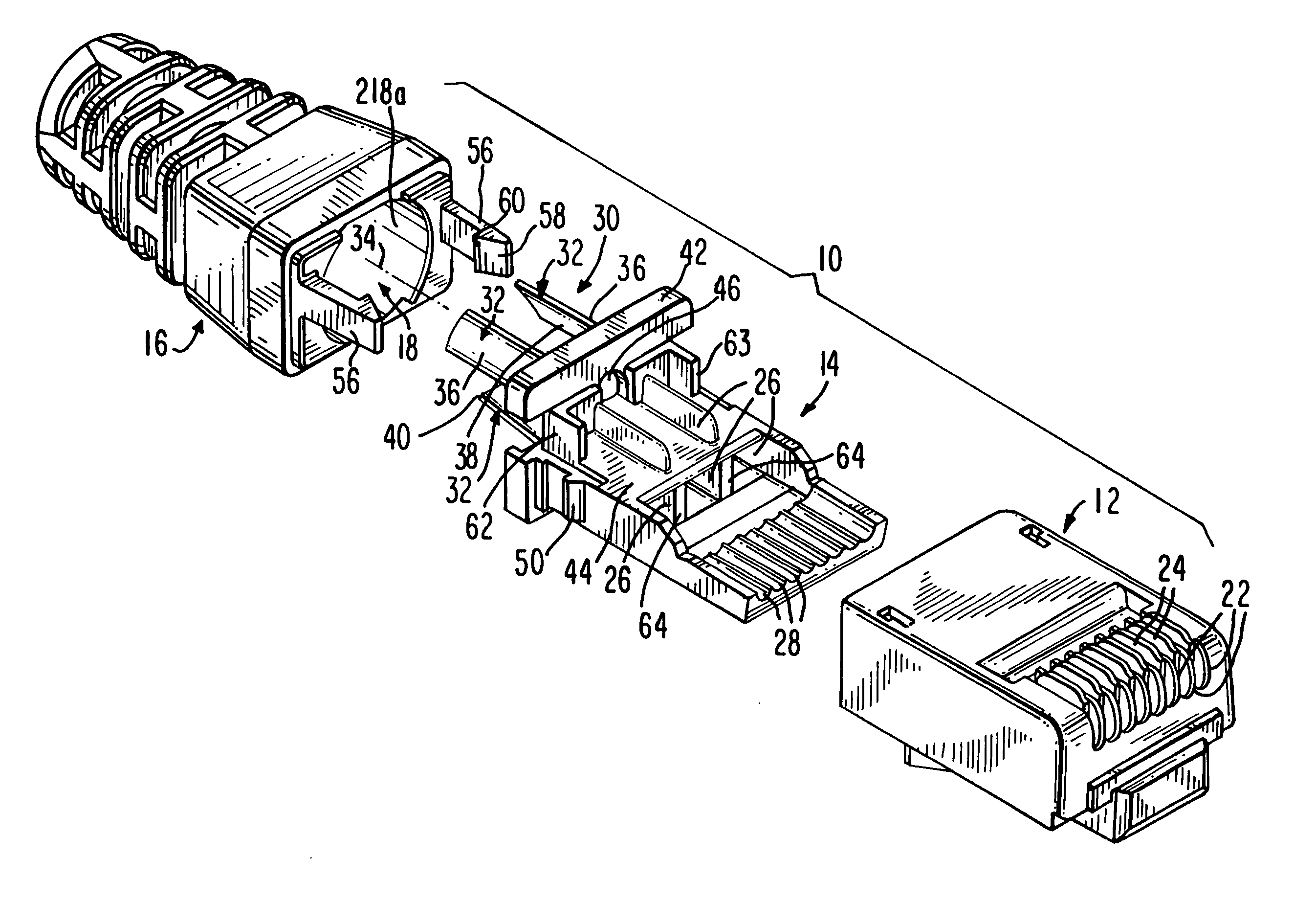
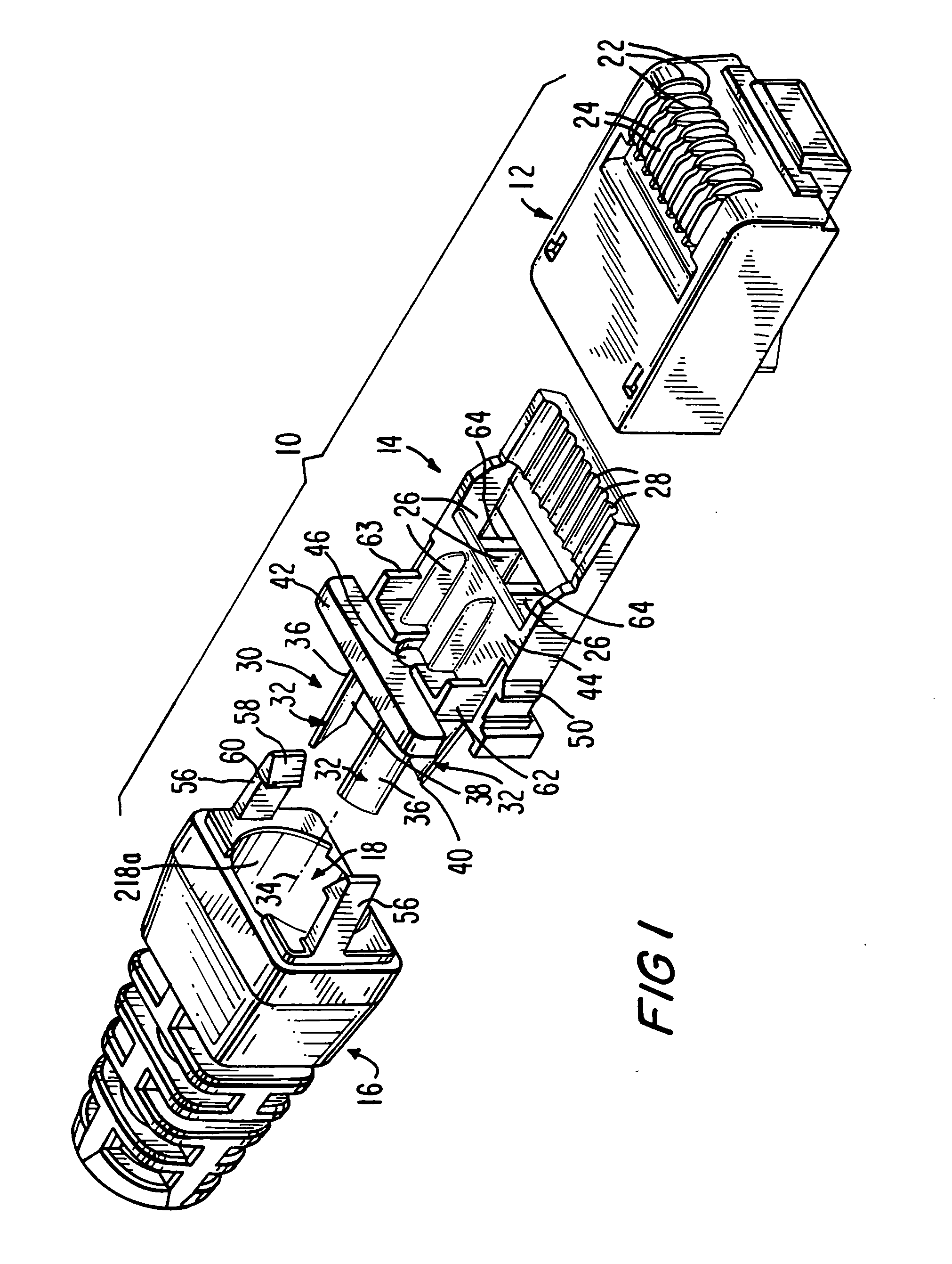
[0025] Referring to the accompanying drawings wherein like reference numerals refer to the same or similar elements, FIG. 1 shows a first embodiment of a modular plug in accordance with the invention designated generally as 10. The plug 10 is designed as a Cat 6 plug, i.e., meets the specific communications industry requirements for a modular plug capable of operating at frequencies up to 250 MHz. The plug 10 includes a housing 12 constructed for insertion into a mating connector such as a jack, a wire aligner 14 for aligning wires of a cable 8 terminated by the plug 10 and a strain relief member 16 defining a channel 18 through which the cable 8 passes.

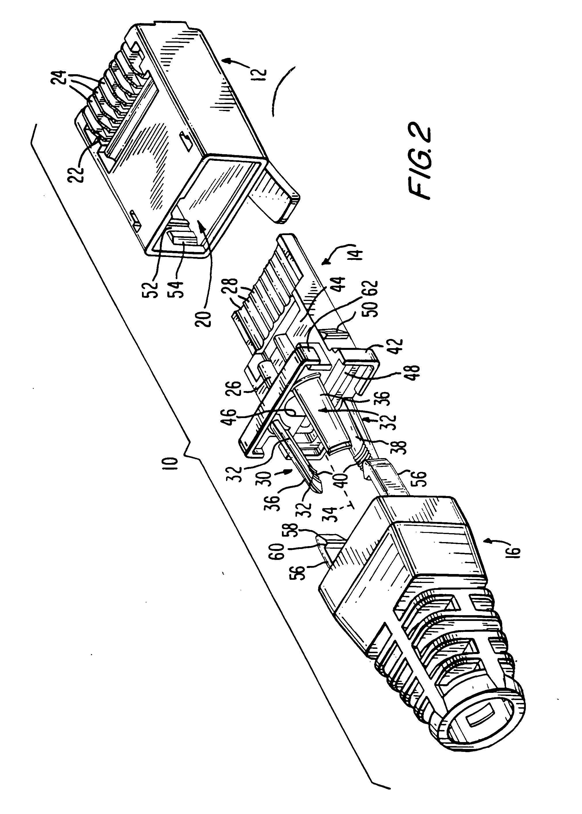
[0026] Housing 12 includes a longitudinally extending cavity 20 opening at a rear of the housing 12. A front end of the wire aligner 14 is arranged in the cavity 20. A plurality of slots 22 are arranged at a front end of the housing 12 and each receives a contact blade 24. Housing 12 also includes other features typical of modular p...


PUM


Abstract

Modular plug for terminating a cable having twisted signal pairs of wires including a plug housing having contact blade-receiving slots at a front end and defining a longitudinally extending cavity opening at a rear end and a strain relief member defining a channel for receiving the cable. A wire aligner is interposed between the strain relief member and the housing and arranged at least partially in the cavity. The wire aligner aligns the wires of the cable into specific position relative to the slots and crimps the cable when received in the channel of the strain relief member. To crimp the cable, the wire aligner is formed with retention fingers which exert an inwardly directed force against the cable when receive din the channel of the strain relief member.

Description

FIELD OF THE INVENTION [0001] The present invention relates generally to the field of modular plugs for terminating cables and more particularly, to a modular plug of the Category 6 type for terminating communication cables. [0002] The present invention also relates to a combined wire aligner and strain relief member for cable-terminating modular plugs and modular plugs including the same. BACKGROUND OF THE INVENTION [0003] Communication networks generally transmit data at a high frequency over cables having a plurality of twisted signal pairs of wires. For example, according to currently accepted performance standards, Category 5 (“Cat 5”) products operate at frequencies up to 100 MHz and Category 6 (“Cat 6”) products operate at frequencies up to 250 MHz over Unshielded Twisted Pair (UTP) cables that contain eight individual wires arranged as four twisted signal pairs. When data is transmitted via alternating current in a typical telecommunication application at such high frequenci...

Claims


Application Information

Patent Timeline
Patent Type & Authority Applications(United States)
IPC IPC(8): H01R13/58H01R24/00
CPCH01R13/5816H01R23/10H01R13/5825H01R24/64
Inventor MECKLEY, TED R.COLANTUONO, ROBERT G.MAROWSKY, RICHARD D.
Owner BEL FUSE
Why Eureka
Try Eureka