
Pulse wave analyzing method, pulse wave analyzing software, and so forth

Inactive Publication Date: 2005-05-19
COLIN MEDICAL TECH
View PDF2 Cites 26 Cited by
  • Summary
  • Abstract
  • Description
  • Claims
  • Application Information

AI Technical Summary

Benefits of technology

[0036] (6) This index can be used to evaluate cardiac functions quickly, by being compared with a sum (ΣΔV) of respective changes of volumes of arteries during one heartbeat.

Problems solved by technology

Thus, it could be said that the information is not sufficiently utilized.
Since, however, an analyzing method implemented by the conventional software is not satisfactorily well schemed, it cannot extract sufficiently much information from the pulse wave.
This means that the measured pulse wave data are not sufficiently utilized.

Method used


Image

  • Pulse wave analyzing method, pulse wave analyzing software, and so forth
  • Pulse wave analyzing method, pulse wave analyzing software, and so forth
  • Pulse wave analyzing method, pulse wave analyzing software, and so forth

Examples


first embodiment

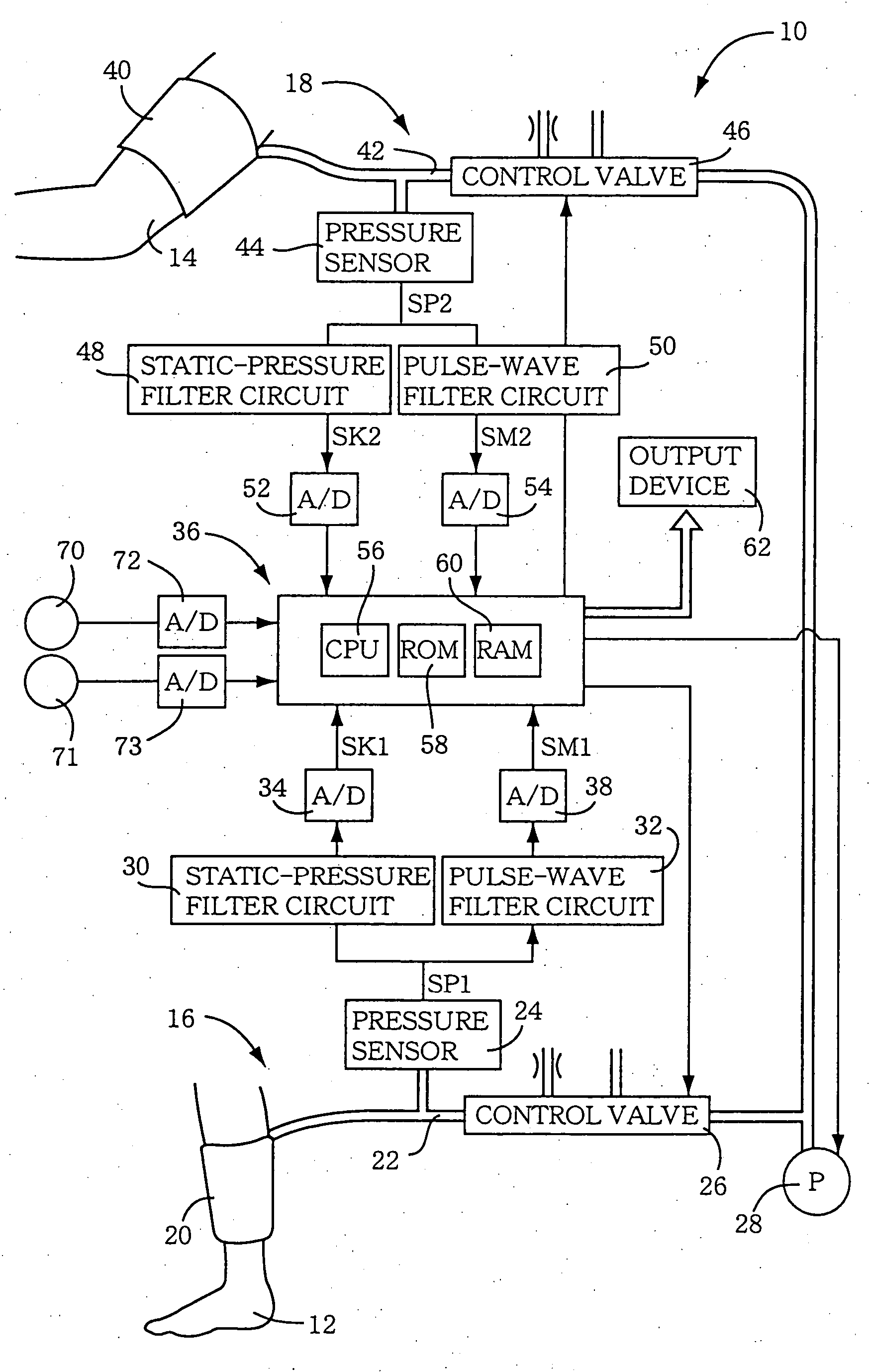
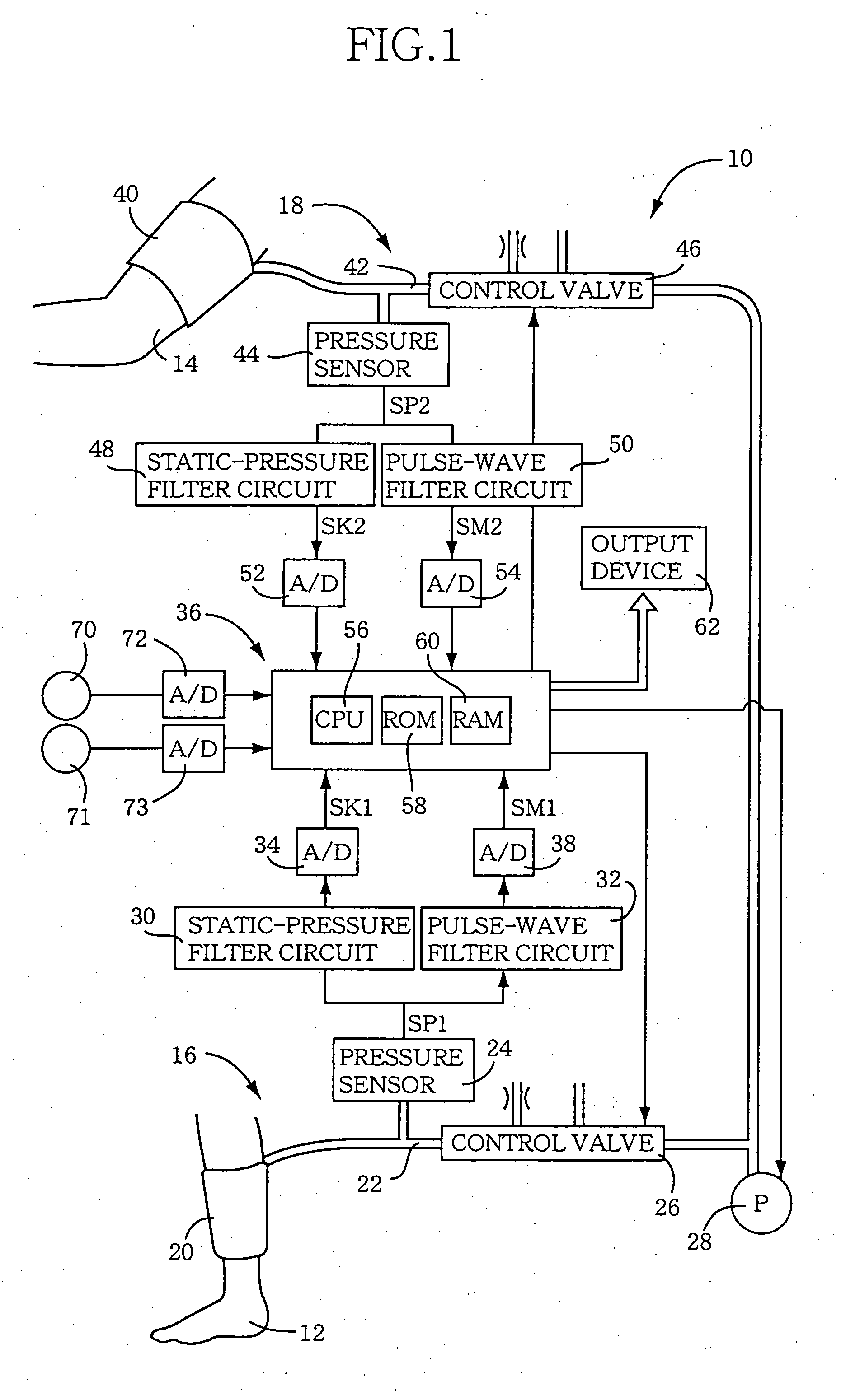
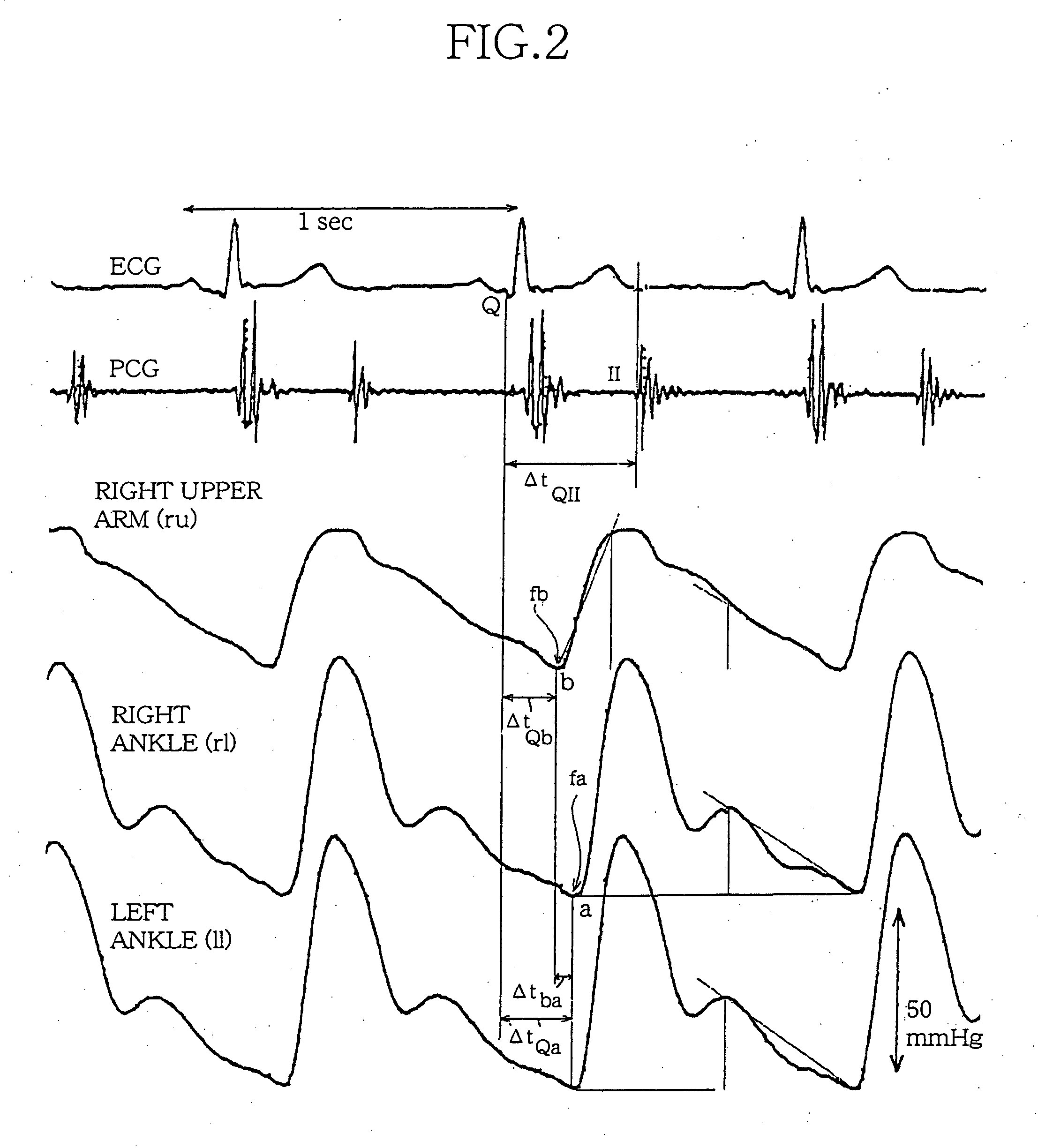
[0095] First, this computer may be provided by the electronic control device 36 of the above-described apparatus 10. More specifically described, since the control device 36 is timewise supplied with the pulse wave data from the upper and lower limbs, the electrocardiogram data, and the phonocardiogram data, the control device 36 can concurrently process those data and calculate the parameters concerning the arteries.

second embodiment

[0096] Alternatively, the above computer may be one that can read digital data outputted, and recorded on the recording medium, by the output device 62, and process those data. In this case, a common computer may be used to read the digital data from the recording medium and calculate, based on the data, the parameters concerning the arteries.

[0097] Algorithm of Software

[0098] Next, there will be described an example of an algorithm that can implement the above-described calculating methods, by reference to FIG. 3.

[0099] First, initial data concerning a living subject (including, e.g., a stature, a body weight, a body surface area, a circulating blood volume, an arterial blood volume, lAb, lAa, and lba) are inputted (S100).

[0100] Subsequently, the measured data concerning the heart and the arteries are inputted based on the pulse waves, the electrocardiogram, and the phonocardiogram (S110). Those data may be inputted (1) while the apparatus 10 performs the measuring operation, o...

example 1

ACTUAL MEASUREMENT EXAMPLE 1

[0110] Next, function evaluation indexes of an actual living subject are calculated using the above-described formulas.

[0111] Case 1

[0112] She is a nineteen-year-old, active and healthy high-school girl. She showed the following values: mPm=73 mmHg; PPm=48 mmHg; heart rate=67 b / min; Cm=504 cm / sec; Um=120 cm / sec; Ve=204 ml; ΣΔV=233 ml; Vst=74 ml; Co=4.9 L / min; CI=3.4 L / min / m2; Rci=0.701 cm; hA=0.107 cm; total blood flow rate increase Q=1369 ml / sec (The value (FRlu) of the left upper limb, substituted by the value (FRru) of the right upper limb, was added. This applies to the following values, if appropriate); FRru=1196 ml / min; FRrl=1098 ml / min; and FRll=783 ml / min. A total blood flow rate of the four limb arteries was 4273 ml / min; EA=4.05×10⁵ Nm−2; and respective Young's modulus values of the four limb arteries were such that Eru=5.91×10⁵ Nm−2, Erl=4.75×10⁵ Nm−2, and Ell=3.82×10⁵ Nm−2. The measured and calculated values, obtained from this case, are trea...


PUM


Abstract

An object of the present invention is to provide a pulse wave analyzing software and a pulse wave analyzing apparatus each of which can extract, from a pulse wave, more information related to an artery. When a series of formulas developed by the Inventor are applied to pulse wave data, electrocardiogram data, and phonocardiogram data that are measured as time elapses, new parameters related to an artery (e.g., a volume elasticity modulus (Km), a Young's modulus (EA), etc.) can be calculated. These parameters can be used to evaluate functions of a living being in a non-invasive, accurate, easy, and quick fashion.

Description

TECHNICAL FIELD [0001] The present invention relates to a software etc. that utilizes a pulse wave propagating in an artery of a living being and evaluates information related to the artery. BACKGROUND ART [0002] There has conventionally been known (from, e.g., Japanese Patent Application Publication No. 2001-161649 or Japanese Patent Application Publication No. 2001-340306) an apparatus that measures a pulse wave of an artery of an upper limb, a lower limb, etc. of a living being, extracts, from the pulse wave data, information related to an arterial system of the living being, and evaluates a condition of the arterial system (e.g., a degree of arteriostenosis). Since this apparatus is non-invasively used on the living being and takes a considerably short time only to measure the pulse wave, the living being feels little discomfort. Thus, the apparatus enjoys a high usability. [0003] However, the data obtained from the pulse wave by a software employed by the above-indicated appara...

Claims


Application Information

Patent Timeline
IPC IPC(8): A61B5/0205A61B5/021A61B5/022A61B5/024A61B5/0285
CPCA61B5/02007A61B5/0205A61B5/021A61B5/02125A61B5/6828A61B5/024A61B5/0285A61B5/6824A61B5/022
Inventor NAKAYAMA, RYU
Owner COLIN MEDICAL TECH
Learn More