Method and apparatus for controlling ablation in refractive surgery

a refractive surgery and ablation depth technology, applied in the field of refractive surgery, can solve the problems of reducing the quality of vision in scotopic conditions, reducing the accuracy of ablation results, so as to reduce the induced aberration, the effect of accurate outcome and reducing spatial overlap

Inactive Publication Date: 2005-05-19
THE CLEVELAND CLINIC FOUND
View PDF7 Cites 143 Cited by
  • Summary
  • Abstract
  • Description
  • Claims
  • Application Information

AI Technical Summary

Benefits of technology

[0023] 7. a sorting algorithm to order the pulse sequence to minimize spatial overlap between consecutive or temporally nearby laser pulses.
[0024] In accordance with the present invention, a control algorithm produces a more accurate outcome and reduces induced aberrations for the full range of correction of myopia, hyperopia, astigmatism, and higher-order aberration.

Problems solved by technology

If the laser ablation patterns used in photorefractive keratectomy (PRK) and laser in-situ keratomileusis (LASIK) procedures to correct the refractive error are not properly selected, post-procedure aberrations can result that reduce quality of vision in scotopic conditions.
Prior known transition zone designs have provided continuity of ablation depth but do not guarantee continuity in slope and curvature.
Known formulations of ablation patterns are also algebraically complex in that they result from differences between spherical surfaces.
However, spherical surface formulations contain spherical aberrations.
In addition, spherical surfaces are not ideal refractive surfaces.
However, these proposed ablation patterns only correct for spherical myopia and are not useful to correct myopic astigmatism, hyperopia, hyperopic astigmatism, or mixed astigmatism.
However, it is believed that this procedure results in secondary aberrations greater than the aberration corrected.

Method used


Image

  • Method and apparatus for controlling ablation in refractive surgery
  • Method and apparatus for controlling ablation in refractive surgery
  • Method and apparatus for controlling ablation in refractive surgery

Examples


Embodiment Construction

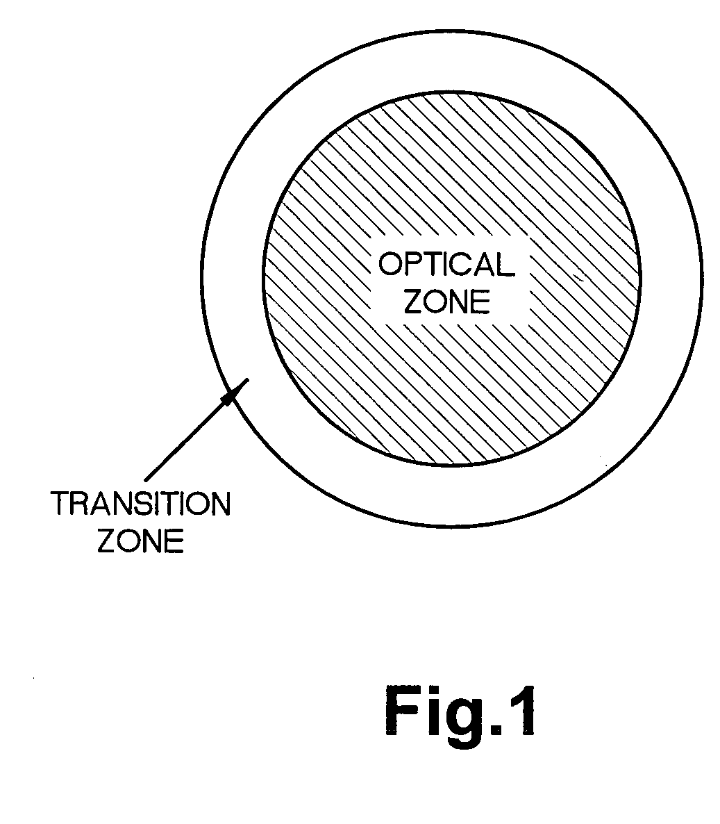
[0053] Ablation designs, in accordance with the present invention, start with a target corneal surface height change needed to correct preoperative refractive error or aberration. This is referred to as the correction map Δh. The correction map is specified within a central optical zone (“OZ”). The OZ preferably centers on the line of sight and matches the maximum size of the pupil. In accordance with the present invention, the correction map for the correction of myopia, hyperopia, and astigmatism are parabolic. This reduces the induction of aberrations compared with spherical and cylindrical corrections.

[0054] Referring to FIG. 1, the OZ is surrounded by a transition zone (“TZ”) to produce a smooth, continuous blend in ablation depth, slope, and curvature with the surrounding cornea. The OZ and TZ together constitute the entire ablation zone (“AZ”). In accordance with the present invention, a constrained iterative deconvolution algorithm is used to compute the ablation map for th...


PUM


Abstract

The present invention relates to laser ablation patterns to correct refractive errors of the eye (60) such as nearsightedness, farsightedness, astigmatism, and higher order aberrations of the eye (60). The laser ablation patterns used to control the laser (10) prevent induced aberrations by compensating for post-procedure epithelial smoothing. The position of laser pulses (12) is also controlled to optimize the achievement of the intended ablation pattern.

Description

BACKGROUND OF THE INVENTION [0001] Laser refractive surgery is often used to correct refractive errors, such as myopia, hyperopia, and astigmatism, in a patient's eyes. Refractive errors are also called lower-order aberrations of the eye. The eye also may have higher-order aberrations caused by irregularities in the cornea or crystalline lens. More recently, laser correction is also applied to higher-order aberrations such as coma, spherical aberrations, and other aberrations. Ideally, the laser refractive surgery should accurately remove the refractive error and not induce additional aberrations. The refractive errors and aberrations are removed through corneal ablation. The laser device follows a predetermined ablation pattern designed to correct the refractive errors and aberrations. These patterns are referred to as ablation patterns. [0002] If the laser ablation patterns used in photorefractive keratectomy (PRK) and laser in-situ keratomileusis (LASIK) procedures to correct the...

Claims


Application Information

Patent Timeline
Patent Type & Authority Applications(United States)
IPC IPC(8): A61F9/008A61F9/01G02B26/08
CPCA61F9/008A61F9/00806A61F2009/00842A61F2009/00844G02B26/0816A61F2009/00872A61F2009/0088A61F2009/00897A61F2009/00859
Inventor HUANG, DAVIDSHEKHAR, RAJTANG, MAOLONG
Owner THE CLEVELAND CLINIC FOUND
Why Eureka
Try Eureka