Foundry mold handling system with multiple dump outputs and method

Active Publication Date: 2005-05-26
HUNTER AUTOMATED MACHINERY
View PDF11 Cites 17 Cited by
  • Summary
  • Abstract
  • Description
  • Claims
  • Application Information

AI Technical Summary

Benefits of technology

[0006] It is a general objective of the present invention to provide a better

Problems solved by technology

While these foregoing patents disclose significant technological innovations and improvements in the mold handling system art and have advanced automation in the mold making industry, there are still deficiencies existing with the apparatus and methods associated with making and handling sand molds to produce metal castings.
One issue is that problems with the formation of sand molds or quality problems with castings being formed may not be discovered until a late stage.
For example, each time a metallurgical mixture of molten metal is created in a ladle, it often takes a

Method used


Image

  • Foundry mold handling system with multiple dump outputs and method
  • Foundry mold handling system with multiple dump outputs and method
  • Foundry mold handling system with multiple dump outputs and method

Examples


Embodiment Construction

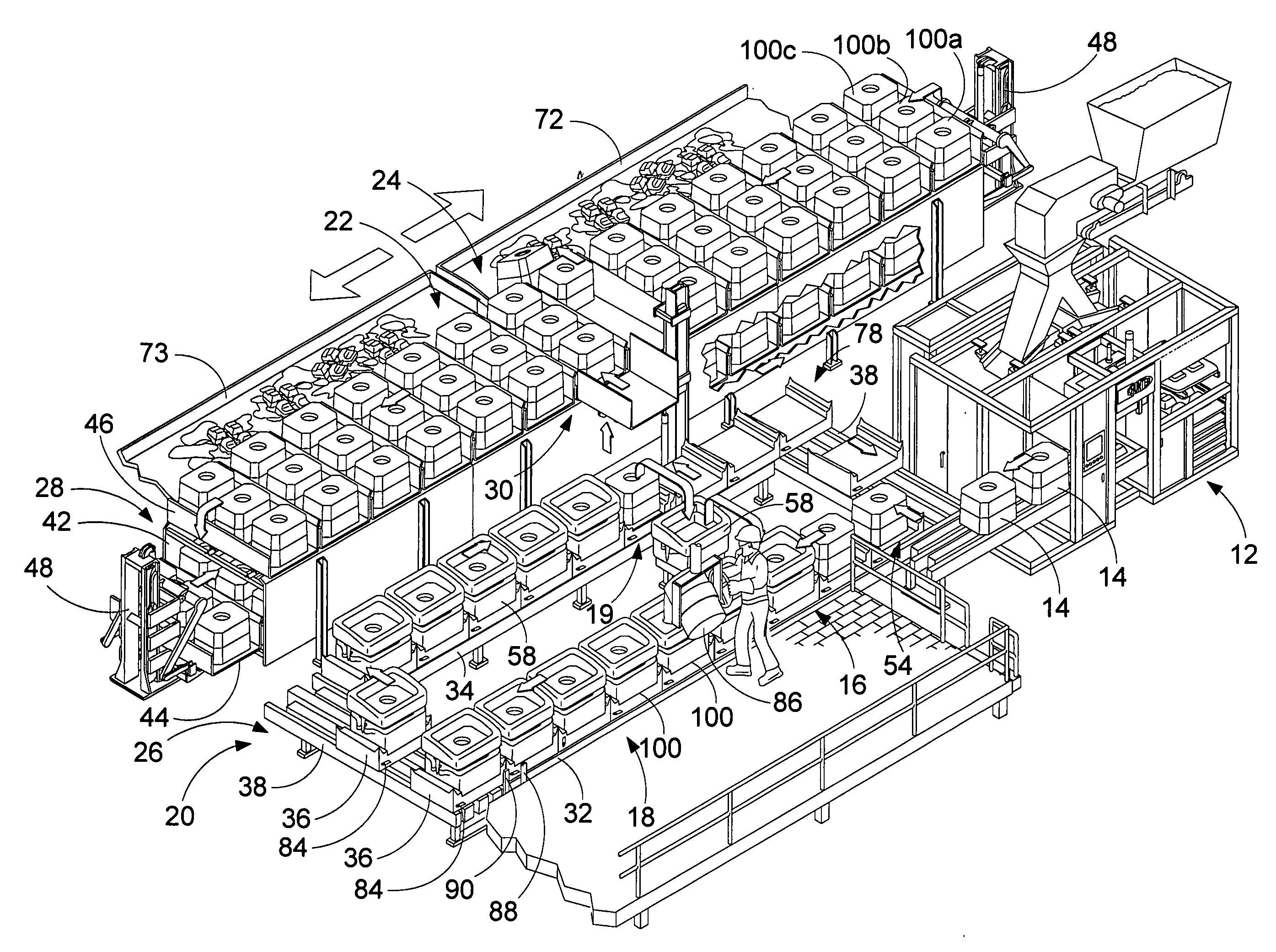
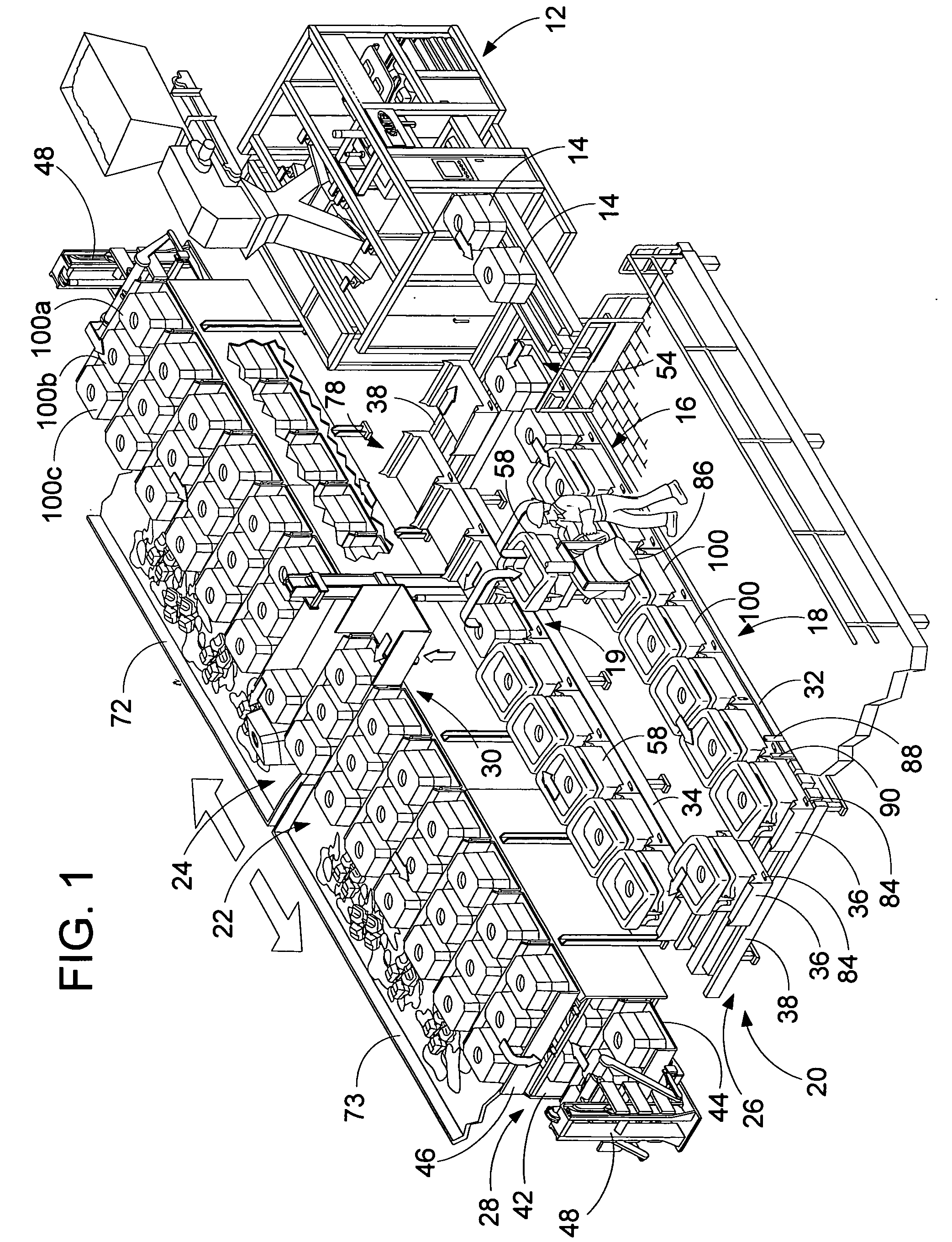
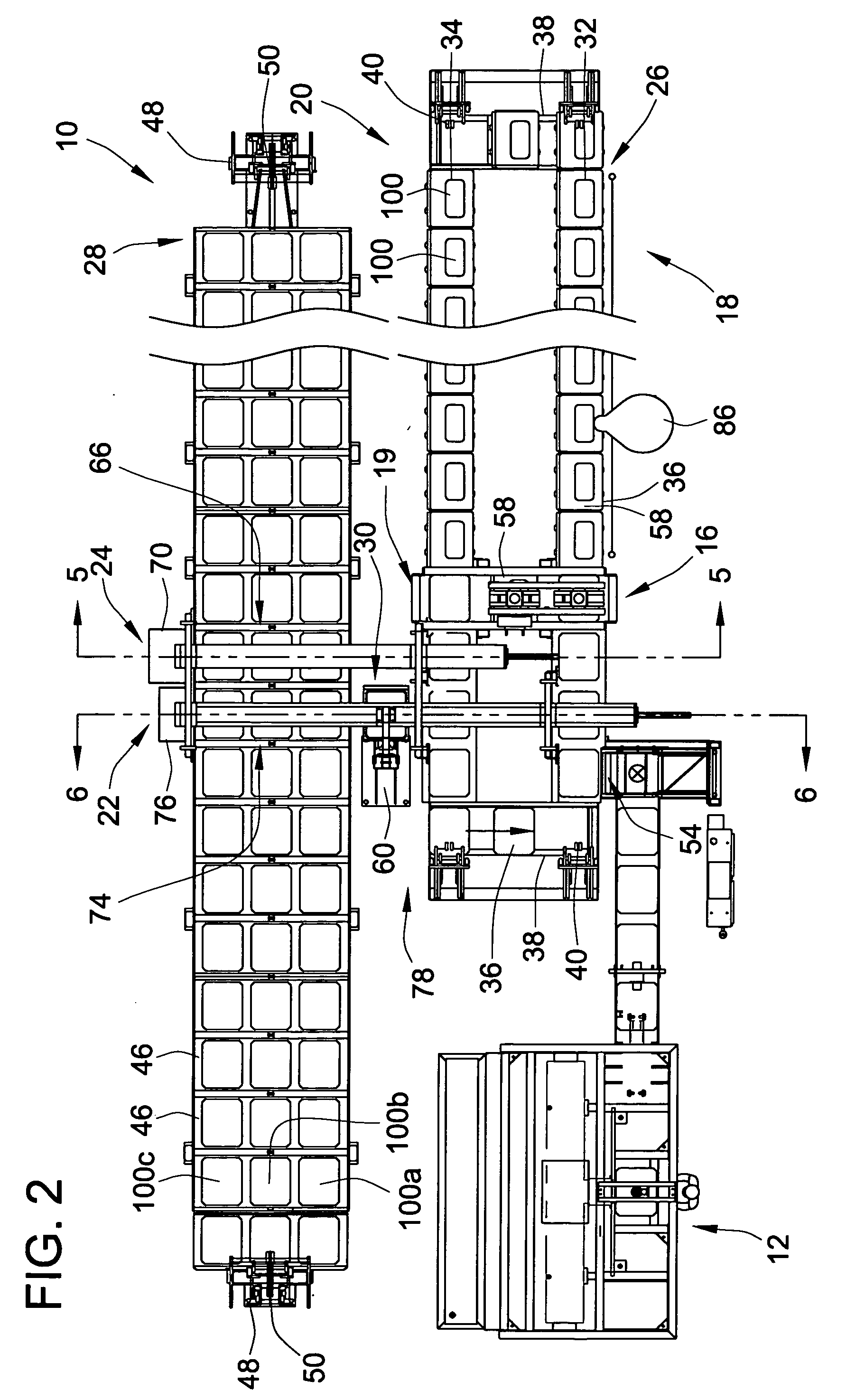
[0021] Referring no to FIG. 1, an embodiment of the present invention is generally depicted as a sand mold handling system 10 that is connected to a mold forming station 12 whereat sand molds 12 are formed. The sand mold forming station 12 is shown as an automatic matchplate mold making machine, which may be a machine as disclosed in pending U.S. application Ser. No. 10 / 133,824 to Hunter, which is hereby incorporated by reference in its entirety. In the molding machine, sand is compressed within a mold flask about a matchplate. This machine may be configured to be readily capable of changing matchplates or other sand mold forming parameters (e.g. squeeze and blow settings) during continuous operation to form molds with differing mold characteristics. The sand mold handling system 10 generally comprises a weight and jacket installation station 16, a pouring station 18, a weight and jacket removal station 19, mold handling conveyor 20 and a discharge station, which contrary to the pri...


PUM

PropertyMeasurementUnit
Timeaaaaaaaaaa
Responsivityaaaaaaaaaa

Abstract

A mold handling system for carrying and transporting sand molds comprises a mold handling conveyor with multiple mold exits to provide different outputs for the sand molds. The mold handling system may include flags which can be used to mark selected molds to segregate the sand molds into different groups. A control system responds to flag sensors and tracks the molds to selectively control output of sand molds through the mold exits. Methods of handling sand molds using a mold handling system are also disclosed.

Description

CROSS-REFERENCE TO RELATED PATENT APPLICATIONS [0001] This patent application claims the benefit of U.S. Provisional Patent Application No. 60 / 520,583, filed Nov. 17, 2003.FIELD OF THE INVENTION [0002] This invention pertains to foundry equipment and methods, and more particularly to foundry mold handling systems and methods for handling sand molds. BACKGROUND OF THE INVENTION [0003] Examples of mold handling systems are disclosed in the following U.S. Pat. No. 3,827,549 to Hunter entitled “Extended Cooling Conveyor”; U.S. Pat. No. 4,589,467 to Hunter entitled “Mold Handling System”; U.S. Pat. No. 5,901,774 to Hunter et al. entitled “Linear Mold Handling System With Double-Deck Pouring And Cooling Lines; U.S. Pat. No. 5,927,374 to Hunter et al. entitled “Manufacturing Sand Mold Castings”; U.S. Pat. No. 5,971,059 to Hunter et al. entitled “Molding And Casting Machine”; and U.S. Pat. No. 6,145,577 to Hunter et al. entitled “Linear Mold Handling System”; and pending patent application ...

Claims


Application Information

Patent Timeline
IPC IPC(8): B22C5/16B22C9/02B22C11/02B22D2/00B22D33/02B22D46/00B22D47/02
CPCB22D2/00B22D47/02B22D46/00
Inventor HUNTER, WILLIAM A.HUNTER, WILLIAM G.
Owner HUNTER AUTOMATED MACHINERY
Why Eureka
Try Eureka