Textile product having an integrated sensor for measuring pressure and temperature

a technology of pressure and temperature measurement and integrated sensor, which is applied in the direction of force/torque/work measurement apparatus, instruments, weaving, etc., can solve the problems of large space occupation of individual components, high cost, and inflexible arrangement of individual components with respect to one another

Inactive Publication Date: 2005-05-26
HEIMBACH GMBH & CO KG
View PDF6 Cites 23 Cited by
  • Summary
  • Abstract
  • Description
  • Claims
  • Application Information

AI Technical Summary

Benefits of technology

[0021] SW components are special microacoustic elements and comprise a piezoelectric substrate on whose polished surface are applied metallic structures such as interdigital converters or reflectors. When an alternating voltage is applied to a converter, the voltage is converted by way of the inverse piezo effect into a periodic deformation of the crystal surface. This deformation propagates as an acoustic surface wave (SW). SW transponders require neither wiring or batteries. They are also small, robust, inexpensive, and extremely durable. They withstand, for example, hard radiation, high temperatures, or shock. They are therefore ideal for use at inaccessible locations such as moving or rotating parts. Transmission of the sensor signals can thus be accomplished by radio, thereby making possible even more flexible configuration of the arrangement of the reading electronics system outside the textile product. The static and dynamic measurement of pressure and / or temperature can be read out by means of ideal voltage measurement, inter alia.

Problems solved by technology

A principal disadvantage of this arrangement may be seen in the fact that the individual components, such as the Nd:YAG laser, detector, and analysis computer, are very cost-intensive.
In addition, the individual components require a great deal of space, and their arrangement with respect to one another is relatively inflexible.
The disadvantage of a limited number of measurement points and the inaccessibility of specific process regions exists here as well.
In addition, only positioning errors of the textile product in the paper machine can be detected by means of this measurement assemblage.
It is not possible to measure the speed, pressure, or temperature of the textile product.
The disadvantage of this measurement apparatus is on the one hand that the measurement head must be placed onto the textile product or paper machine felt.
On the other hand, the configuration of the measurement head, with a microwave radiator to measure the quantity of water in the felt and a temperature sensor to measure the temperature of the air sucked through the measurement head into the air conduit, is very complex and cost-intensive.
The number of measurement points is moreover limited, both in structural terms and for cost reasons.

Method used


Image

  • Textile product having an integrated sensor for measuring pressure and temperature
  • Textile product having an integrated sensor for measuring pressure and temperature

Examples


Embodiment Construction

)

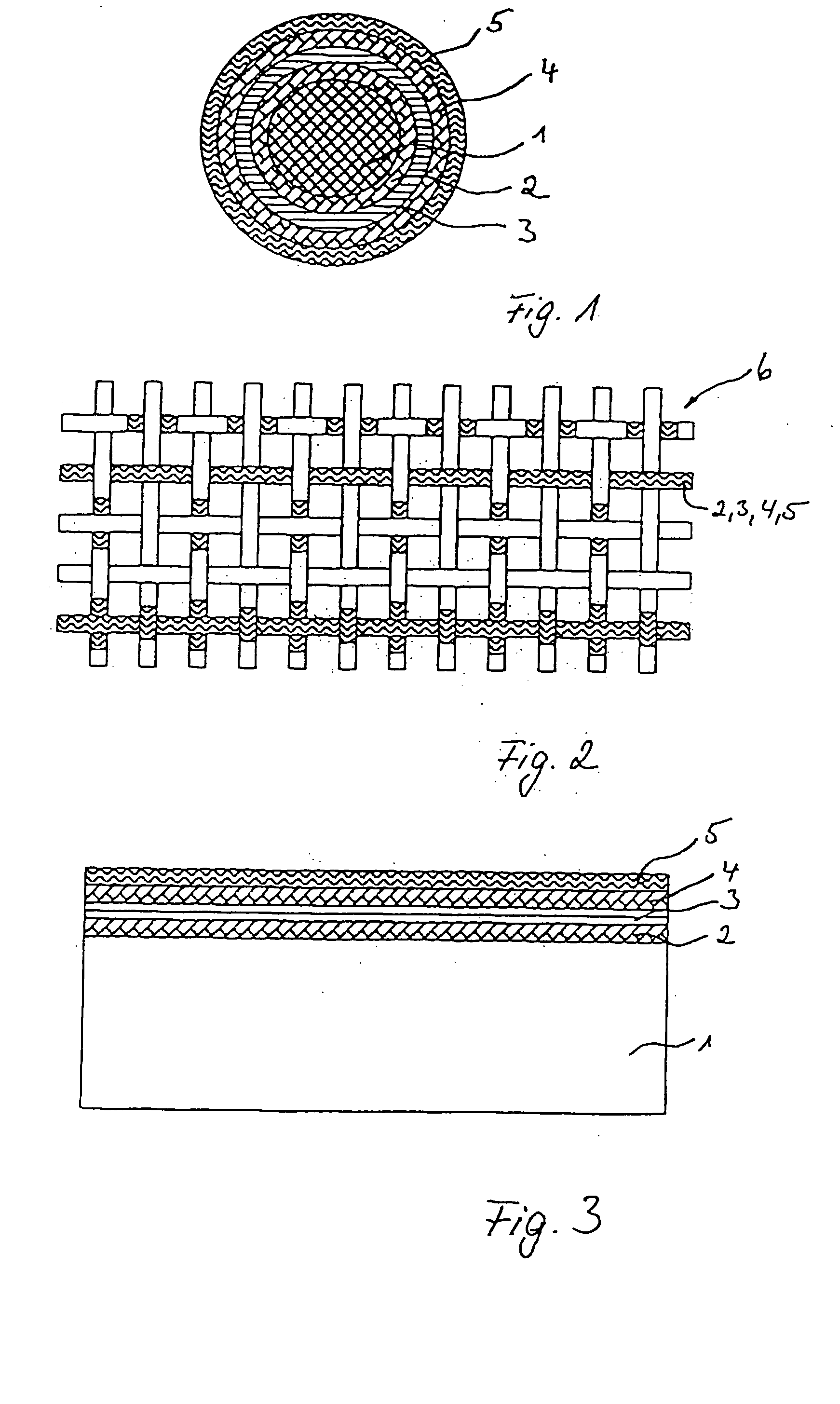
[0026]FIG. 1 is a cross section through a textile product according to the present invention, which in this case is embodied as a support element 1 in the form of a monofilament that is completely surrounded by a first metallization 2. Applied onto this first metallization 2 is a second layer 3 having piezoelectric properties. This is a piezo lacquer comprising a polyvinylidene fluoride copolymer that can be sprayed on or otherwise applied. This layer 3 is then polarized, and a second metallization layer 4 is applied. An insulation layer 5 in the form of a lacquer, in contact against second metallization layer 4, serves to protect metallization layer 4 located below it from functional impairments and damage during operation.

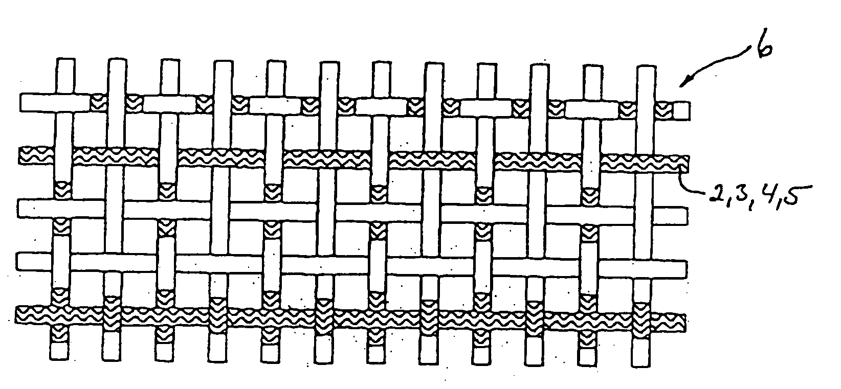
[0027]FIG. 2 shows, by way of example, one possible arrangement of support element 1 with sensor layers 2, 3, 4, 5 in a dryer fabric 6. Pressure plays a subordinate role in dryer fabrics 6, i.e. it is substantially constant. The temperature or temperature diffe...


PUM

PropertyMeasurementUnit
thicknessaaaaaaaaaa
pressureaaaaaaaaaa
temperatureaaaaaaaaaa

Abstract

The invention concerns a textile product (6) for use in a paper machine, having a monofilament or a profiled structure as support element (1) on which is arranged a layered sensor for measuring pressure and/or temperature, and is characterized in that the sensor is constituted from at least three layers (2, 3, 4), the second layer (3) having piezoelectric properties and the layers (2, 4) in contact against the second layer (3) forming electrodes that are couplable or coupled to an analysis device. The invention further concerns a method for producing such a textile product.

Description

CROSS-REFERENCE TO RELATED APPLICATIONS AND CLAIM TO PRIORITY [0001] This application claims the benefit of application number 03 018 343.8, filed Aug. 13, 2003, in the European Patent Office, the disclosure of which is incorporated herein by reference.FIELD OF THE INVENTION [0002] The invention concerns a textile product for use in a paper machine, having a monofilament or a profiled structure as support element on which is arranged a layered sensor for measuring pressure and temperature, as well as a method for producing a support element for a textile product. BACKGROUND OF THE INVENTION [0003] A textile product of this kind is known, for example, from U.S. Pat. No. 6,158,576. The known textile product comprises in its matrix a sensor that is excited by means of Nd:YAG laser radiation and as a result emits radiation having a wavelength different from the excitation wavelength. This radiation is detected by means of a detector in the vicinity of the textile product, thus making it...

Claims


Application Information

Patent Timeline
Patent Type & Authority Applications(United States)
IPC IPC(8): D03D1/00G01L5/00D03D15/00D03D15/02D21F1/00D21F7/08G01D21/02G01K13/08G01L1/16H01L41/113
CPCD21F1/0027D21F7/08G01L1/16Y10S162/90Y10S162/903Y10S162/902H01L41/1132H10N30/302G01D21/02
Inventor BEST, WALTERGERUNDT, SEBASTIAN
Owner HEIMBACH GMBH & CO KG
Why Eureka
Try Eureka