Radiation image pick-up device, radiation image pick-up method, and radiation image pick-up system

a technology of radiation image and pick-up device, which is applied in the direction of television system, radioation controlled device, instruments, etc., can solve the problems of high diagnosis efficiency, long time before a doctor obtains an x-ray image of a patient, and heavy burden on patients, so as to reduce correction errors and accurate correction

Inactive Publication Date: 2005-05-26
CANON KK
View PDF17 Cites 75 Cited by
  • Summary
  • Abstract
  • Description
  • Claims
  • Application Information

AI Technical Summary

Benefits of technology

[0039] The present invention is devised to solve the problem and has as its object the provision of a radiation image pick-up device, a radiation image pick-up method, and a radiation image pick-up system which reduce correction errors caused by a difference in the amount of X-ray absorption and achieve accurate correction when correcting a radiographed object image, the difference being made by a splash, a foreign matter and so on.

Problems solved by technology

Under such circumstances, because of a film development process of X-ray image pick-up devices using the conventional film system, it takes a long time before a doctor obtains an X-ray image of a patient.
These factors interfere with higher efficiency of diagnosis in hospitals and put a heavy burden on patients, resulting in a serious difficulty in establishing a new medical society for the future.
Although Gd2O2S:Tb3+ can be mass-manufactured and is inexpensive, a large amount of light is scattered because Gd2O2S:Tb3+ is a particulate scintillator, resulting in a low resolution.
The smaller atomic number of a material, the smaller attenuation coefficient, resulting in difficulty in absorbing an X-ray (higher transmittance).
Hence, it is difficult to prevent the entry of a foreign matter in a process of manufacturing a photodetector array and a fluorescent screen.
Current technology has not found any means for eliminating the splash.
Thus, like abnormal growth caused by a foreign matter, white correction causes a white correction error according to a change in the tube voltage characteristic.
Other scintillators similarly have white correction errors caused by foreign matters.
Moreover, a direct radiation image pick-up device using no scintillator has a similar white correction error.
The generated thickness distribution changes an amount of X-ray absorption like the splash of CsI, causing a white correction error.

Method used


Image

  • Radiation image pick-up device, radiation image pick-up method, and radiation image pick-up system
  • Radiation image pick-up device, radiation image pick-up method, and radiation image pick-up system
  • Radiation image pick-up device, radiation image pick-up method, and radiation image pick-up system

Examples


embodiment 1

[0079] Embodiment 1 of the present invention will be described below in accordance with the accompanying drawings.

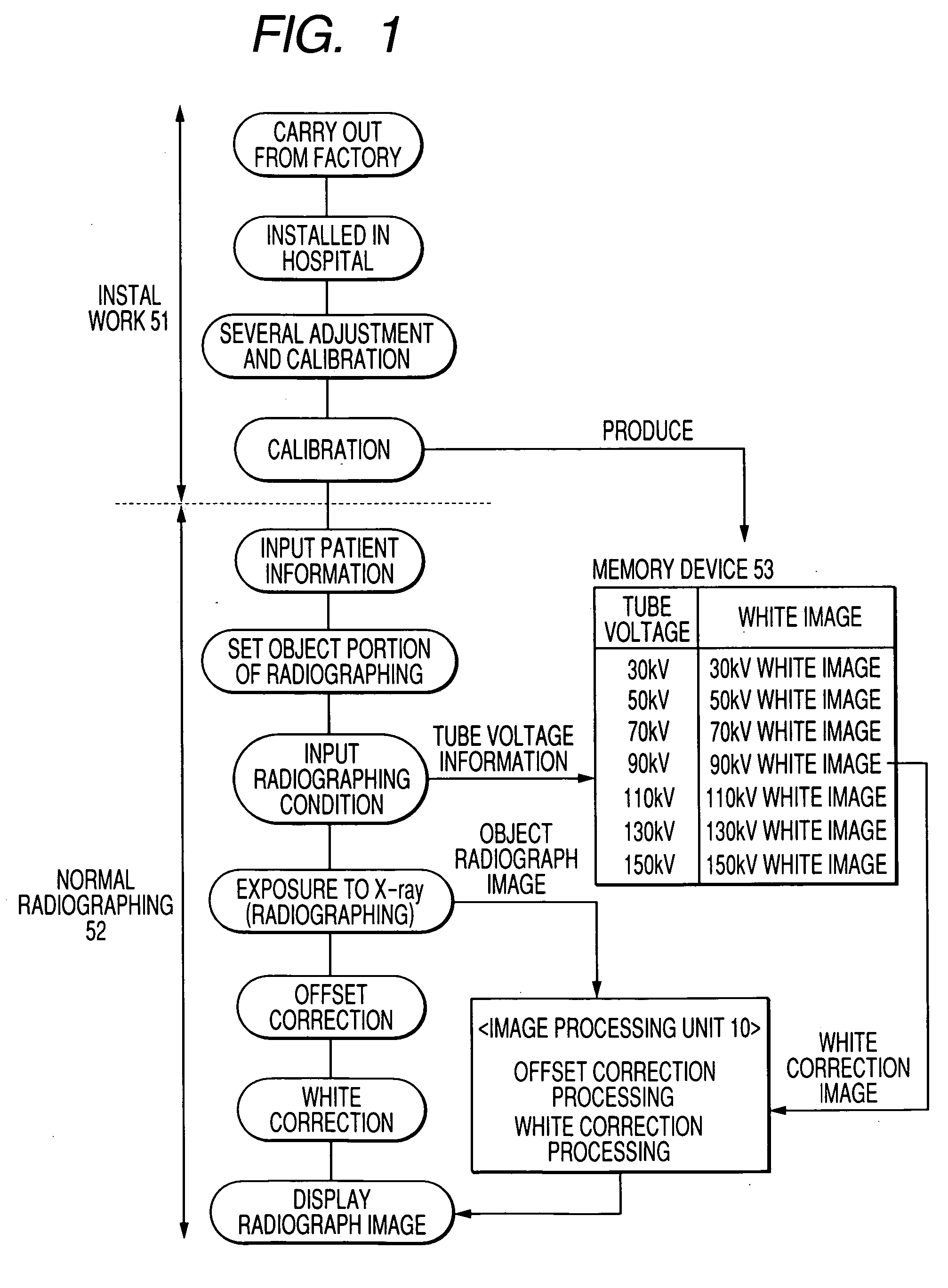
[0080]FIG. 1 is a flowchart showing an X-ray image pick-up method of Embodiment 1.

[0081] A digital X-ray image pick-up device having been carried out from a factory is installed in a hospital and subjected to several adjustments such as image formation. Thereafter, calibration is performed. The calibration is performed with no radiographed object and obtains an output of about a half of the saturation of the digital X-ray image pick-up device. Further, the calibration is performed in an area exhibiting linearity relative to a dosage (mAs value). An average value of two or more radiographed images is used to reduce quantum noise and so on. For example, an average image of ten radiographed images is used as a white image for correction.

[0082] In Embodiment 1, calibration is performed every 20 kV of tube voltage, and white images for correction are obtained at seven poin...

embodiment 2

[0090] Embodiment 2 of the present invention will be described below in accordance with the accompanying drawings.

[0091]FIG. 4 is a flowchart showing an X-ray image pick-up method of Embodiment 2.

[0092] A digital X-ray image pick-up device having been carried out from a factory is installed in a hospital and subjected to several adjustments such as image formation. Thereafter, calibration is performed. The calibration is performed with no radiographed object and obtains an output of about a half of the saturation of the digital X-ray image pick-up device. Further, the calibration is performed in an area exhibiting linearity relative to a dosage (mAs value). An average value of two or more radiographed images is used to reduce quantum noise and so on. For example, an average image of ten radiographed images is used as a white image for correction.

[0093] In Embodiment 2, calibration is performed every 40 kV of tube voltage, and white images are obtained at four points of 30 kV, 70 ...

embodiment 3

[0101] Embodiment 3 of the present invention will be described below in accordance with the accompanying drawings.

[0102]FIG. 17 is a flowchart showing an X-ray image pickup method of Embodiment 3. FIG. 16 is a calibration radiographing diagram of Embodiment 3.

[0103] Embodiment 3 of the present invention is different from Embodiment 1 only in a calibration radiographing method.

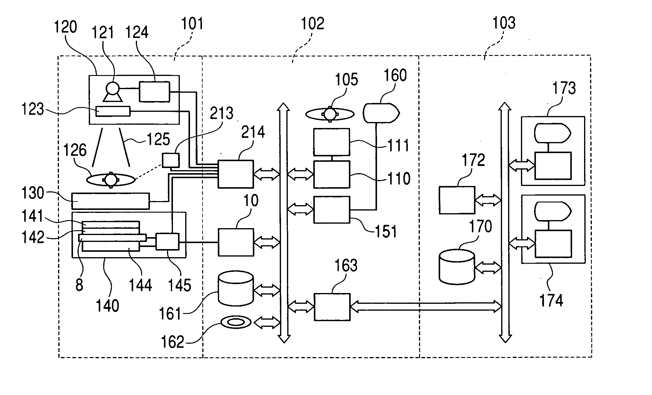
[0104] A digital X-ray image pick-up device having been carried out from a factory is installed in a hospital and subjected to several adjustments such as image formation. Thereafter, calibration is performed. In Embodiment 1, calibration is performed with no radiographed object, whereas a water phantom is used in Embodiment 3. In FIG. 16, reference numeral 121 denotes an X-ray vessel, reference numeral 140 denotes an X-ray detector, and reference numeral 222 denotes the water phantom.

[0105] Generally in calibration, radiographing is performed with no radiographed object. Since a radiation is absorbed by an...


PUM


Abstract

A plurality of correction images are obtained while changing the radiation energy of an incident radiation in the absence of an object. Subsequently, an object image is obtained in the presence of the object by emitting the radiation to the object. Then, the object image is corrected by using a correction image obtained under a radiation energy condition closest to the radiation energy of the obtained object image.

Description

BACKGROUND OF THE INVENTION [0001] 1. Field of the Invention [0002] The present invention relates to a radiation image pick-up device, a radiation image pick-up method and a radiation image pick-up system which correct a radiographed object image. [0003] 2. Related Background Art [0004] Currently, X-ray image pick-up devices used for medical diagnosis mainly use a so-called film system in which an X-ray is emitted to a human body, the X-ray having passed through the human body is applied to a scintillator for converting the X-ray into a visible radiation, and a fluorescence is exposed to a film. [0005] However, more efficient diagnosis and more accurate medical devices are strongly demanded in hospitals of the world as well as in Japan which is becoming an aging society. Under such circumstances, because of a film development process of X-ray image pick-up devices using the conventional film system, it takes a long time before a doctor obtains an X-ray image of a patient. When a pat...

Claims


Application Information

Patent Timeline
Patent Type & Authority Applications(United States)
IPC IPC(8): G01T1/20A61B6/00G01T1/24G01T1/29H01L27/14H01L31/09H04N5/32
CPCA61B6/583G01T1/2928A61B6/5258
Inventor TAKENAKA, KATSUROENDO, TADAOKAMESHIMA, TOSHIOYAGI, TOMOYUKI
Owner CANON KK
Why Eureka
Try Eureka