Projection type image display device

a projection type, image display technology, applied in the direction of static indicating devices, picture reproducers using projection devices, instruments, etc., can solve the problems of increased risk of burns, and burns to the retina of the eye, so as to achieve brighter images

Inactive Publication Date: 2005-05-26
SONY CORP
View PDF5 Cites 32 Cited by
  • Summary
  • Abstract
  • Description
  • Claims
  • Application Information

AI Technical Summary

Benefits of technology

[0023] In order to solve the above problems, it is an object of the present invention to provide a projection type image display device that can ensure safety and display brighter images.

Problems solved by technology

When its laser power is high, the light causes a burn on the retina of the eye.
Hei 3-65916 However, if the laser beam before being applied to the screen is directly looked at accidentally and an amount of light of the laser beam is large, the retina of the eye may be burned.
The risk is related to energy density (W / m2) of the laser light, exposure duration, and size of an image point on the retina.
The higher the energy density (W / m2) of the laser light, the longer the exposure duration, and the smaller the size of the image point on the retina, the greater the risk of a burn.
However, as shown by the above consideration, considering laser safety for the eye, the system cannot increase laser light intensity (W / m2).
Consequently the system cannot display brighter images.

Method used


Image

  • Projection type image display device
  • Projection type image display device
  • Projection type image display device

Examples


Embodiment Construction

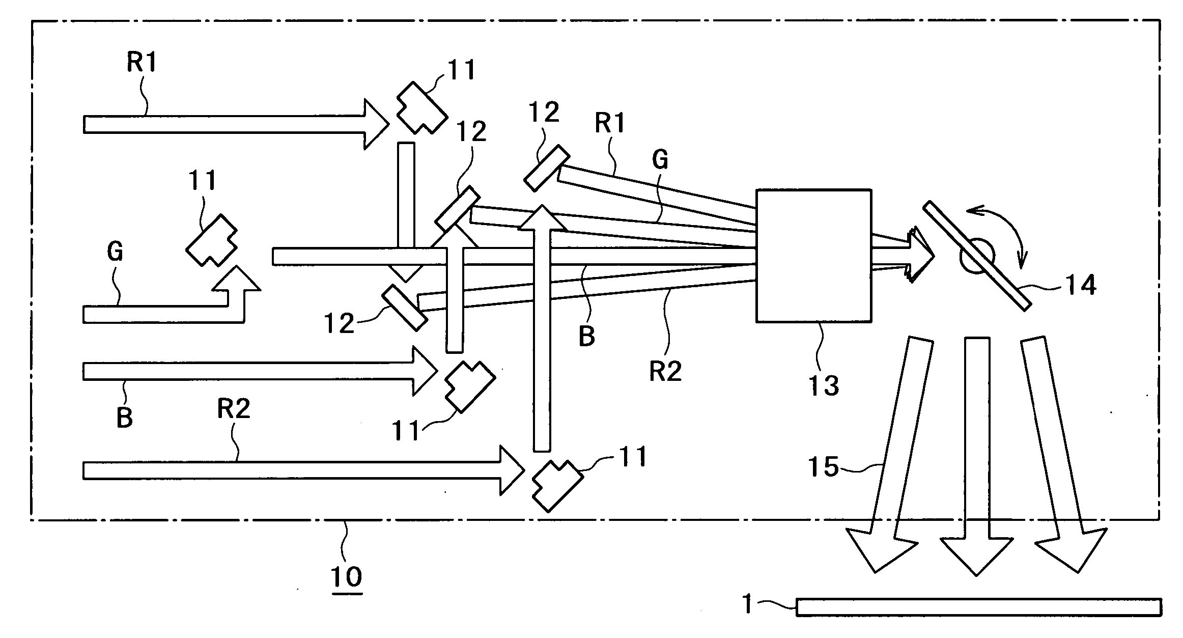
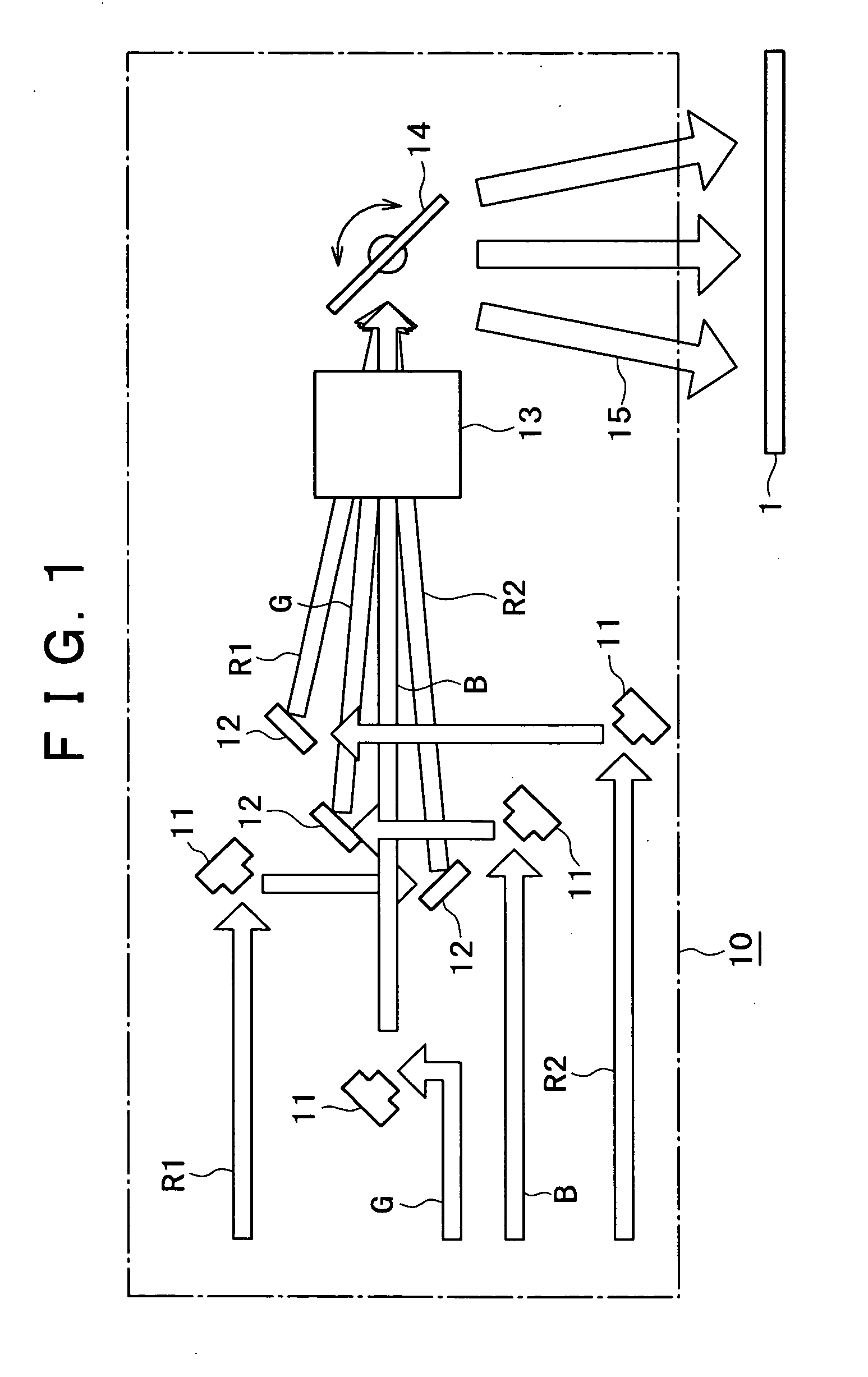
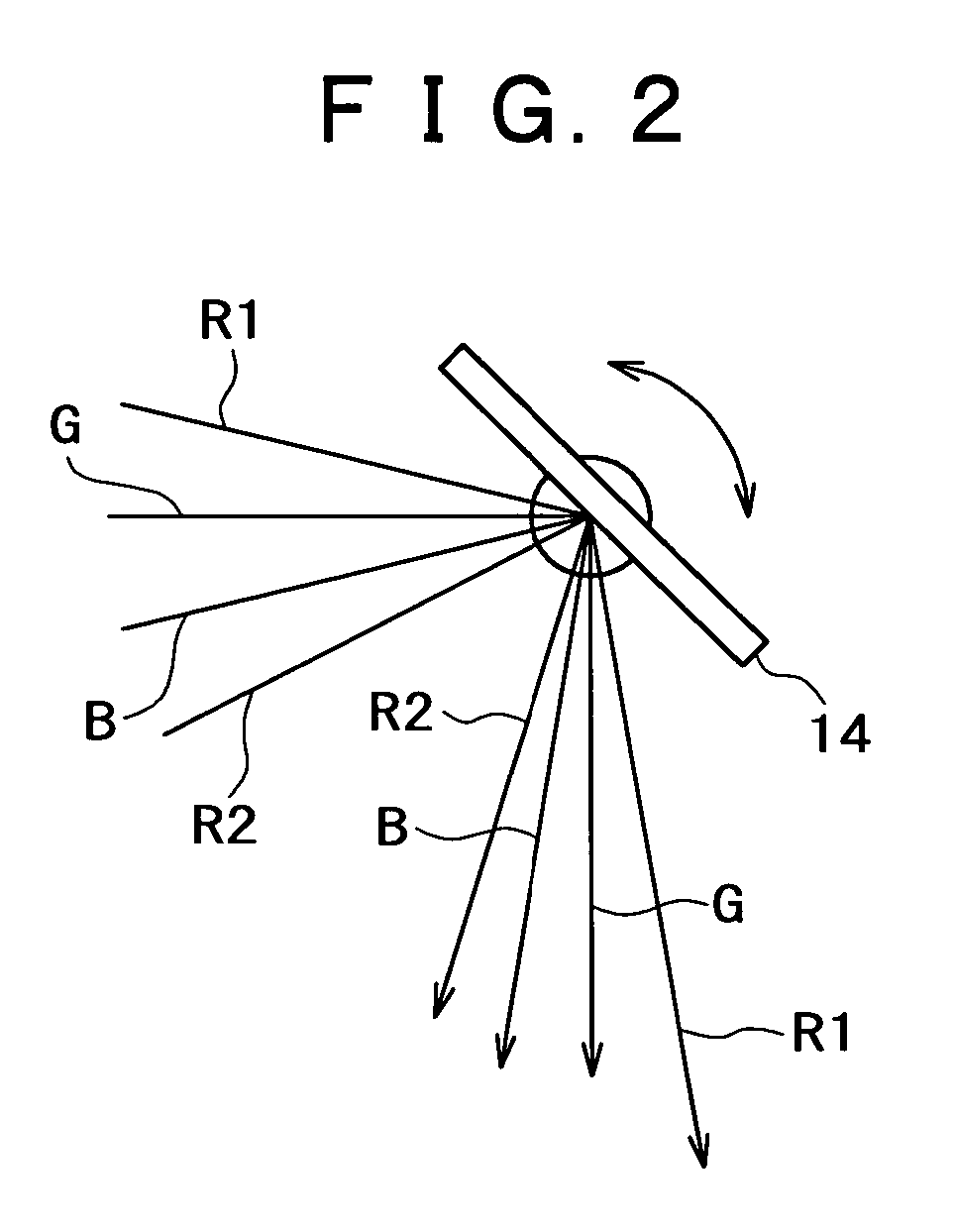
[0044]FIG. 1 is a schematic diagram of configuration of a projection type image display device according to one embodiment of the present invention.

[0045] The projection type image display device 10 displays an image on a screen 1 by using pieces of laser light of red R1 and R2, green G, and blue B colors from a laser light source not shown in the figure. The pieces of laser light are extended in a vertical direction of an image area of the screen 1, horizontally scanning these pieces of laser light R1, R2, G, and B, and thus irradiating the screen 1 with the pieces of laser light R1, R2, G, and B. The two pieces of laser light R1 and R2 are used for red laser light.

[0046] The projection type image display device 10 includes GLV (Grating Light Valve) elements 11, mirrors 12, a projecting lens 13, and a scanning mirror 14. The GLV elements 11 modulate the pieces of laser light of the different colors R1, R2, G, and B from the laser light source into laser beams extended long one-di...


PUM


Abstract

A projection type image display device is formed including projecting means for projecting an image onto a screen for image display by scanning laser light. The laser light includes a plurality of laser beams. The projecting means irradiates a substantially identical position on the screen with the plurality of laser beams with a time difference. An image signal applied to each of the laser beams has a time difference such that a preceding laser beam is delayed with respect to a succeeding laser beam so as to correspond to the time difference in irradiation.

Description

BACKGROUND OF THE INVENTION [0001] The present invention relates to a projection type image display device for making image display using a laser as a light source. [0002] A projection type image display device, that is, a so-called projector device is known as an image display device capable of large screen display. [0003] A projection type image display device that displays images by using a laser as a light source and scanning a laser beam has been considered. The projection type image display device has advantages of providing ease of modulation with an image signal and good color reproducibility, and ensuring sufficient brightness, for example (see Patent Document 1, for example). [0004] Laser light is collimated light emitted from a very small light emission point and having a small angle of divergence. Therefore, if the light directly enters the eye, the light concentrates as a small spot on the retina of the eye. When its laser power is high, the light causes a burn on the r...

Claims


Application Information

Patent Timeline
Patent Type & Authority Applications(United States)
IPC IPC(8): G03B21/00G02B26/10G09G3/02H04N9/31
CPCG03B21/00G03B21/005H04N9/3135
Inventor KOJIMA, AKIHIRO
Owner SONY CORP
Why Eureka
Try Eureka