
Photonic crystal laser sources for chemical detection

a photonic crystal and laser source technology, applied in the field of chemical detection, can solve the problems of not providing sufficient sensitivity for detecting a particular substance, limiting the application of planar photonic crystals, and not using photonic crystal cavities to provide sensitive detection of chemicals

Active Publication Date: 2005-05-26
CALIFORNIA INST OF TECH
View PDF7 Cites 34 Cited by
  • Summary
  • Abstract
  • Description
  • Claims
  • Application Information

AI Technical Summary

Benefits of technology

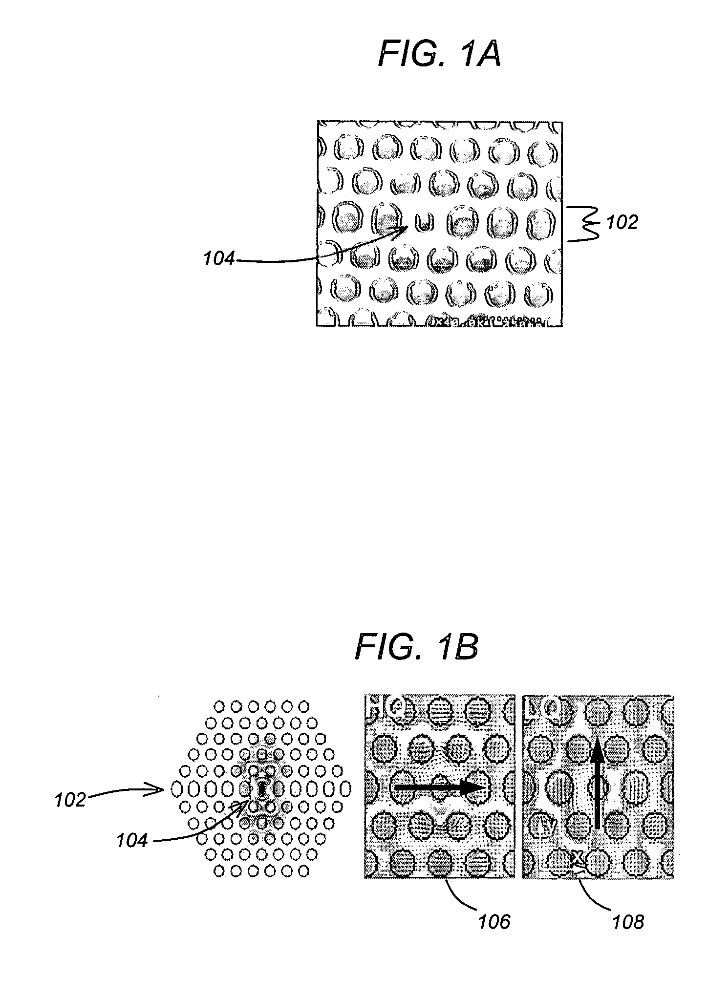
[0015] The invention provides the ability to utilize photonic crystal lasers that permit the introduction of analyte within the peak of the optical field of a lasing mode. Accordingly, the unique design of the laser cavity geometry (i.e., comprising photonic crystal) in combination with the ability to place the anlayte directly into the cavity provides the capability to conduct high-resolution spectroscopy with single-molecule sensitivity. In this regard, the nanocavity lasers of the invention may be used to perform spectroscopic tests on femtoliter volumes of analyte.

Problems solved by technology

However, such measurements may be inaccurate, require substantial amounts of analyte to perform the analysis, and may not provide sufficient sensitivity for detecting a particular substance.
Until recently, the applications of planar photonic crystals have been restricted to large-scale integration of optical wavelength division multiplexing (WDM) components for telecommunications.
However, to date, photonic crystal cavities have not been used to provide sensitive detection of chemicals.
Further, prior art spectroscopy has many limitations including requiring the use of large amounts of analyte and a lack of sensitivity in determining the presence of certain chemicals.

Method used


Image

  • Photonic crystal laser sources for chemical detection
  • Photonic crystal laser sources for chemical detection
  • Photonic crystal laser sources for chemical detection

Examples


Embodiment Construction

[0030] In the following description, reference is made to the accompanying drawings which form a part hereof, and which is shown, by way of illustration, several embodiments of the present invention. It is understood that other embodiments may be utilized and structural changes may be made without departing from the scope of the present invention.

Overview

[0031] One or more embodiments of the invention define photonic crystal lasers that permit the introduction of analyte within the peak of the optical field of the lasing mode. Accordingly, the invention provides a novel cavity design combined with the introduction of analyte into the cavity.

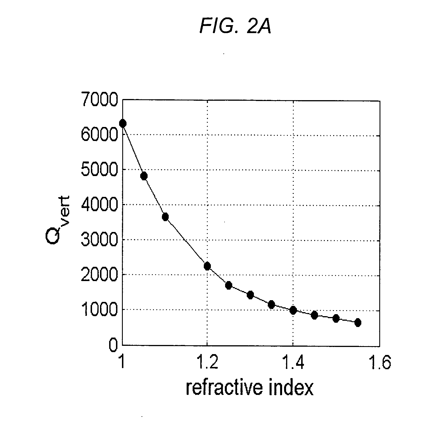
[0032] Photonic crystal lasers may be with different ambient organic solutions. Further, nanocavity lasers can be used to perform spectroscopic tests on sub-femtoliter volumes of analyte, and photonic crystal lasers may be used for high-resolution spectroscopy with single-molecule sensitivity. In addition to precise measurement of the index o...


PUM

PropertyMeasurementUnit
volumesaaaaaaaaaa
wavelength rangesaaaaaaaaaa

Abstract

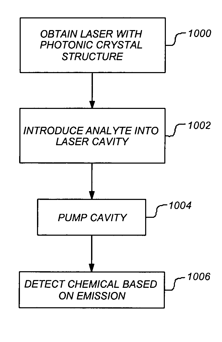
A system, method and apparatus provide the ability to detect a chemical in an analyte. To detect the chemical, the invention utilizes a laser having an open cavity. A photonic crystal lattice structure having a defect defines a suitable geometry for such a cavity. The analyte is introduced directly into a high optical field of the cavity. Thereafter, the cavity is pumped and an emission from the laser is used to detect the presence of the chemical in the analyte.

Description

CROSS-REFERENCE TO RELATED APPLICATIONS [0001] This application claims the benefit under 35 U.S.C. Section 119(e) of the following co-pending and commonly-assigned U.S. provisional patent application(s), which is / are incorporated by reference herein: [0002] Provisional Application Ser. No. 60 / 452,268, filed on Mar. 5, 2003, by Marko Loncar and Axel Scherer, entitled “Photonic Crystal Laser Sources for Chemical Detection,” attorneys' docket number 176.17-US-P1 (CIT-3855-P); and [0003] Provisional Application Ser. No. 60 / 453,185, filed on Mar. 10, 2003, by Marko Loncar and Axel Scherer, entitled “Photonic Crystal Laser Sources for Chemical Detection,” attorneys' docket number 176.17-US-P2 (CIT-3855-P2).STATEMENT REGARDING FEDERALLY SPONSORED RESEARCH AND DEVELOPMENT [0004] The invention was made with Government support under Grant No. BES-011949; ECS-9912039 awarded by the National Science Foundation. The Government has certain rights in this invention.BACKGROUND OF THE INVENTION [000...

Claims


Application Information

Patent Timeline
Patent Type & Authority Applications(United States)
IPC IPC(8): G01J3/30G01N21/39G01N21/41G01N21/77G02B6/122H01SH01S5/04H01S5/10
CPCB82Y20/00G01N21/41G01N2021/391H01S5/105G02B6/1225H01S5/041H01S5/10G01N2021/7776H01S5/11
Inventor SCHERER, AXELLONCAR, MARKO
Owner CALIFORNIA INST OF TECH
Learn More