Microscope

a microscope and microscope technology, applied in the field of microscopes, can solve the problems of difficult use in extremely narrow portions, high cost of associated parts, and difficulty in observation of the bottom part, so as to improve the efficiency of light transmission

Inactive Publication Date: 2005-05-26
KITAMURA JUN +1
View PDF12 Cites 3 Cited by
  • Summary
  • Abstract
  • Description
  • Claims
  • Application Information

AI Technical Summary

Benefits of technology

[0021] The thus constructed microscope of the present invention has a thin sheet-like mirror with a mirror surface formed at an acute angle, so the target object can be vertically examined, while providing a wide horizon, wherein a horizontal observation can be made even in an extremely narrow space.
[0022] In addition, if the thin sheet-like mirror is formed particularly in a convergent taper-like shape, the lighting efficiency will be improved, and at the same time, it is possible to observe a hard-to-observe target object due to its physical space, etc. effectively and appropriately.
[0023] The present microscope can be used as a loupe by combining a thin sheet-like mirror, which is formed at an acute angle at the tip, and a magnifying glass; in addition, by incorporating a compact charge-coupled device camera, and by recording dynamic visual image therewith, it can be utilized as a charge-coupled device-type video microscope, wherein clear video images of the target object of the observation can be obtained.
[0024] In addition, by allowing the thin sheet-like mirror to be detached from and rotated around the hand piece, an easy construction will make it possible that an integrated unit be obtained, and that the gradient of the thin sheet-like mirror to the hand piece can be made variable.
[0025] The thus constructed microscope of the present invention can ensure flare-free image light since the thin sheet-like mirror confines light, and this in turn navigates illuminating light and image light to get them reflected at the mirror surface, which results in diffused light.

Problems solved by technology

However, as means for observing and examining how adequately the soldering balls of the BGA are reliably attached to the board, there are the examinations by electricity transmission and X-ray transmission; nonetheless, the reality is that the associated therewith cost turns out to be extremely high.
As shown in FIG. 24(a), by the conventional examination using the mirror 1, when observing the soldering conditions of the soldering ball 4 of the BGA 3 soldered onto the board 2, the conventional mirror 1 makes it hard to observe the bottom part, where the soldering ball is attached to the board 2 because of the thickness 5 of the mirror; moreover, the depth 6 of the mirror is huge, so the usage in extremely narrow portions is difficult.
Likewise as shown in FIG. 24(b), the conventional examination using a prism 7, the bottom of the part, where the soldering ball 4 is attached to the board 2 can be observed; however, the dimension 8 of the prism itself is formed so that its width becomes rather wide, so the usage in extremely narrow portions is difficult.
Furthermore, with the conventional microscope, when visually observing, for example, the human skin, or the hairline, regions that come in sight are small, and clear images are hard to obtain, which has left a room for further improvements.

Method used


Image

  • Microscope
  • Microscope
  • Microscope

Examples


first embodiment

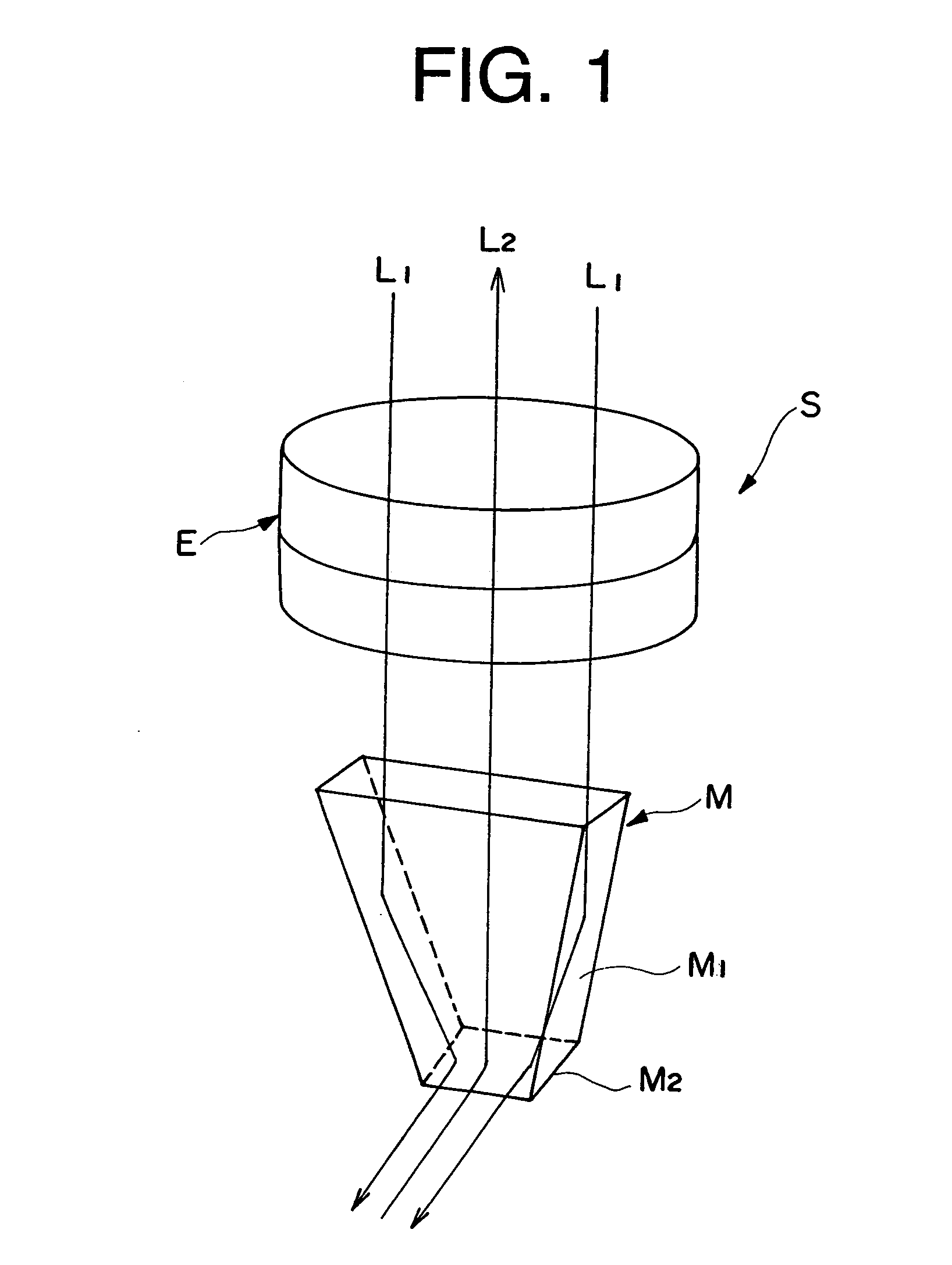
[0053] the present invention is a case where a microscope is used as a loupe, and FIG. 1 is a perspective view showing a principle structure of such a microscope, i.e., a loupe.

[0054] Namely, this microscope S is basically comprised of a magnifying lens E, and a thin sheet-like mirror M, wherein the thin sheet-like mirror M is constructed in such a way that the width of the tip end thereof becomes narrower, and is preferably formed as a convergent taper surface M1, and at the tip thereof there is provided a mirror surface M2 cut out at an acute angle.

[0055] In FIG. 1, when making an observation from an eye lens that is not included in the figure by placing a target object near the mirror surface M2 of the microscope S, and put a loupe in an upright position, and through the mirror surface M2, the reflected image of the target object can be shown as a magnified image.

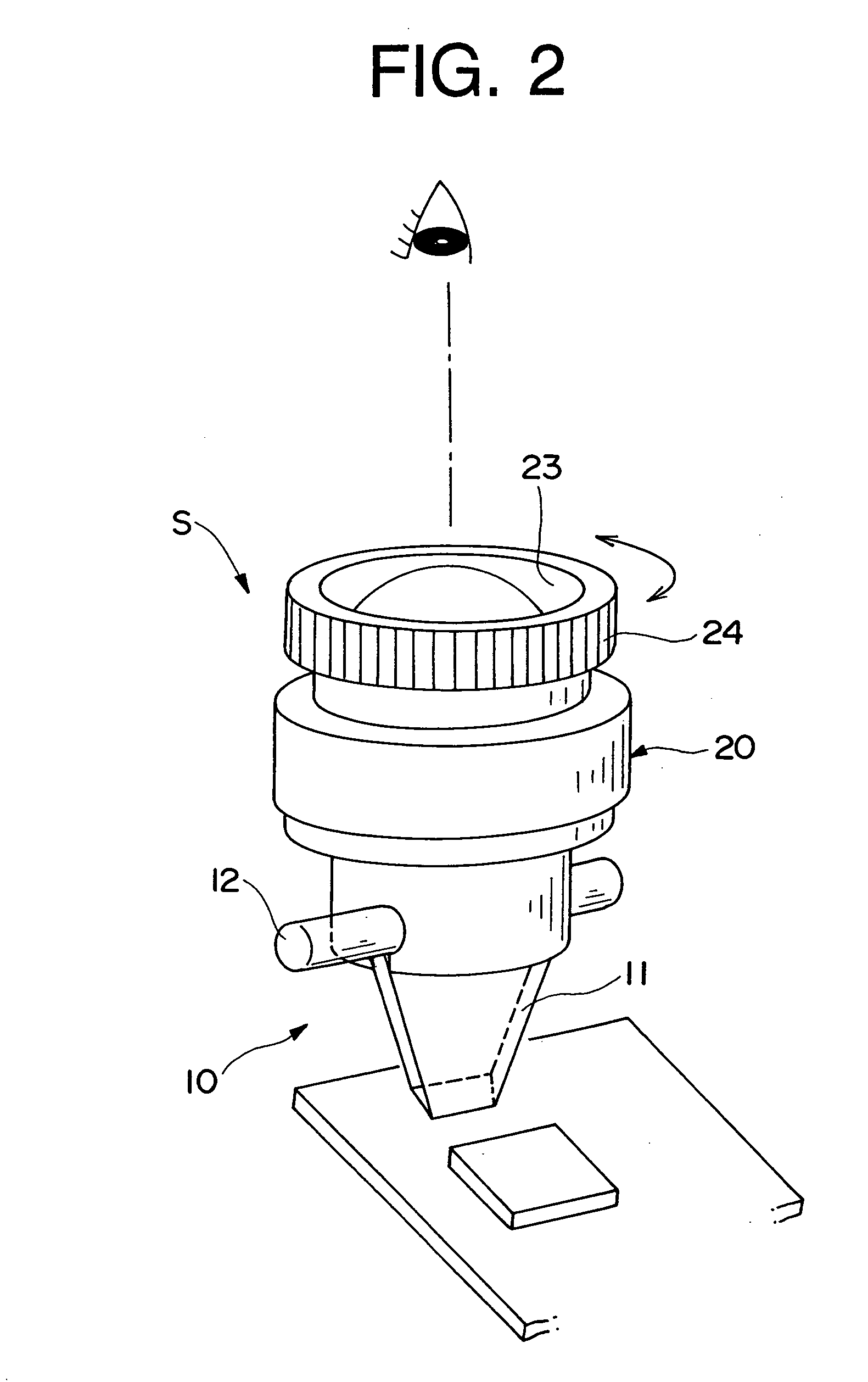
[0056]FIGS. 2 and 3 show application examples when the microscope S is used as a loupe. The thin sheet-like mirror 1...

second embodiment

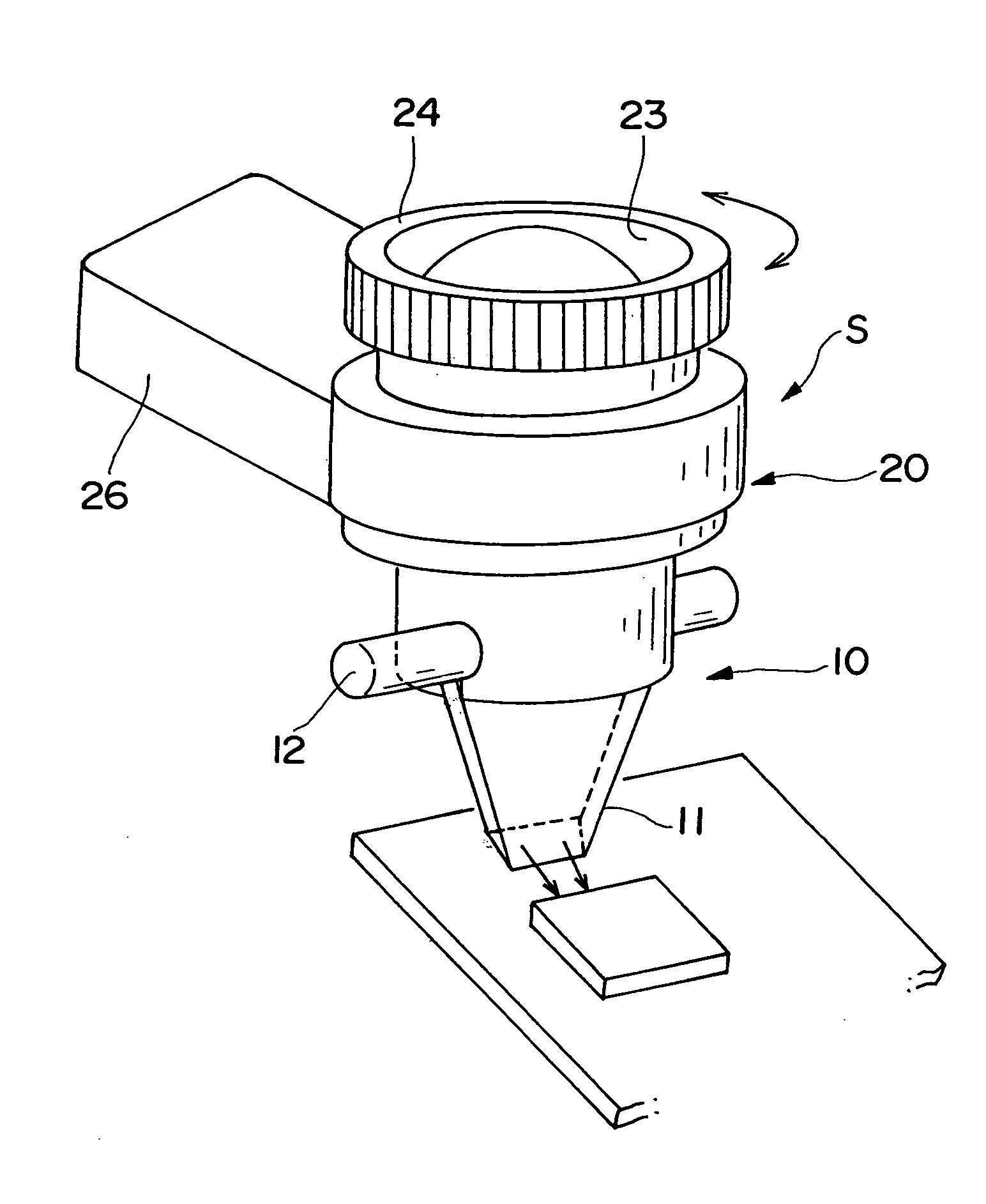
[0066] FIGS. 8 to 10 show the embodiment of a microscope with a lighting device, where a lighting device is incorporated into the hand piece of the microscope. According to this second embodiment, by incorporating a lighting device into the microscope, a target object can be clearly illuminated so that clear images can be obtained.

[0067] In FIG. 8, a battery box 26 housing batteries sticks out horizontally from the hand piece 20, and inside the hand piece 20, as shown in FIGS. 9 and 10, a printed board for source light 31, and lamps for the illumination purpose 32 and 32 that are comprised of, for example, two light emitting elements mounted on the printed board as each parallel, are built in. Each of the lamps for the illumination purpose 32 and 32 are inserted to straight-through bores 28 and 28 that are formed for the illumination purpose inside the hand piece 20, and arranged in an opposing location adjacent to each end region of the base surface 11c of the thin sheet-like mirro...

third embodiment

[0073] Next, the present invention will be illustrated with referring to FIGS. 12 and 13.

[0074] The third embodiment aims at obtaining video images as a charge-coupled device-type video microscope, by incorporating a compact charge-coupled device camera into the microscope.

[0075]FIG. 12 is a schematic cross-sectional view of this charge-coupled device-type video microscope, which is viewed from the front thereof, and FIG. 13 is a schematic cross-sectional view seen from the side thereof.

[0076] This charge-coupled device-type video microscope 100 is comprised of: an optical system 114 that appropriately combines a charge-coupled device (CCD) and a plurality of lenses 113; a focus adjustment mechanism 115 that adjusts the focus of the optical system; a printed board for source light 118, having a light reception bore 116 arranged in a predetermined location with the light axis corresponding to the optical system 114, and materials for illuminating light source 117, such as light emi...


PUM


Abstract

The microscope (S, 100) of the present invention has a hand piece (20, 112), whose tip is mounted with a thin sheet-like mirror unit (M, 10, 130, 220), and around both ends of the base (11c, 131c) thereof is arranged an illuminating light source (32, 117), whereby light is emitted to a target object, image light is lead through the light reception bore (27, 116), to the optical system (114), and is recorded at the CCD camera (111), to obtain video images. The thin sheet-like mirror (M, 11, 131) confines light and navigate it, wherein the width of the mirror can be made narrower like a convergent taper surface (11a, 131a); and it is comprised of a base surface (11c, 131c) where illuminating light comes in and image light goes out, and a mirror surface (11b, 131b) where illuminating light and image light go back and forth, and make the reflection thereof, and the mirror surface (11b, 131b) is slanted to 45 degrees. The microscope may be used as a handy microscope if it is not equipped with a charge-coupled device camera. The microscope can provide a wider horizon, which makes it possible to make a horizontal observation in an extremely narrow space, and can be manufactured at a less expensive price.

Description

TECHNICAL FIELD [0001] The present invention relates to a microscope utilized as a probe for observing an extremely small portion or a microscopic construction of an object; for example, conditions of the BGA (Ball Grid Array), skin, etc. can be observed or examined. Background Technologies [0002] When observing constructions of the skin, conditions of the hair, etc., hand-held microscopes have been frequently used in the fields of medicine, cosmetics, etc. recently, as well as applications of such microscopes have been under development in the field of the manufacturing industry for various machines, and electric and electronic products, or machines, electronic and electric parts to be used therewith. [0003] Among them, when illustrating an example in the case of an ultra-small package BGA soldering, the BGA of this type has come to be more and more frequently used in a wide variety of utilities, such as LSI's in mobile phones, digital camera built-in VTR's, high-performance microp...

Claims


Application Information

Patent Timeline
Patent Type & Authority Applications(United States)
IPC IPC(8): G02B21/00G02B21/08G02B23/26G02B23/00G02B25/02
CPCG02B21/08G02B21/00
Inventor KITAMURA, JUNSAITOH, KIYOSHI
Owner KITAMURA JUN
Why Eureka
Try Eureka