Fuel cell and fuel cell separator

a fuel cell and separator technology, applied in the field of fuel cell and separator, can solve the problems of inability to properly operate, structure failure to prevent the cooling of reactant gas, and inability to supply stable reactant gas

Inactive Publication Date: 2005-05-26
SANYO ELECTRIC CO LTD
View PDF1 Cites 13 Cited by
  • Summary
  • Abstract
  • Description
  • Claims
  • Application Information

AI Technical Summary

Benefits of technology

[0015] In the fuel cell according to the present invention, a coolant, which is originally intended as a means for removing heat of reaction, is supplied on the back of a reactant gas introduction passage. Accordingly, the cooling of the reactant gas is prevented by the heat of the coolant and the temperature of the reactant gas is increased. As a result, condensed water is prevented from being generated in the vicinity of the reaction gas introduction passage and a manifold. It is thus ensured that a reactant gas at a high humidity is supplied to the membrane and electrode assembly. Condensed water is prevented from advancing into the reactant gas introduction passage so that the reactant gas is supplied in a stable manner. Accordingly, it is possible to provide a fuel cell with excellent output stability.
[0017] In the fuel cell separator according to the present invention, a coolant passage is provided on the back of the reactant gas introduction passage. Accordingly, the reactant gas introduction passage is properly heated from the back thereof. This prevents the generation of condensed water due to the cooling of the reactant gas guided from the opening for supply of the reactant gas to the reactant gas introduction passage. Therefore, the reactant gas is supplied to the reactant gas passages via the reactant gas introduction passage in a stable manner. It is thus ensured that the output of the fuel cell is stabilized.

Problems solved by technology

It was found as a result of the study that the related-art structure of a fuel cell cannot properly prevent the supply of a reactant gas from being blocked by condensed water generated from a moistened reactant gas.
Although a cooling water channel is provided in the vicinity of the gas inlet, the structure fails to prevent the cooling of the reactant gas in a supply path that guides the reactant gas from the gas inlet to the gas channel via the gas inlet manifold.
Therefore, stable supply of the reactant gas is prohibited by condensed water generated in the gas inlet manifold or the gas channel.
This results in unstable output characteristics.

Method used


Image

  • Fuel cell and fuel cell separator
  • Fuel cell and fuel cell separator
  • Fuel cell and fuel cell separator

Examples


first embodiment

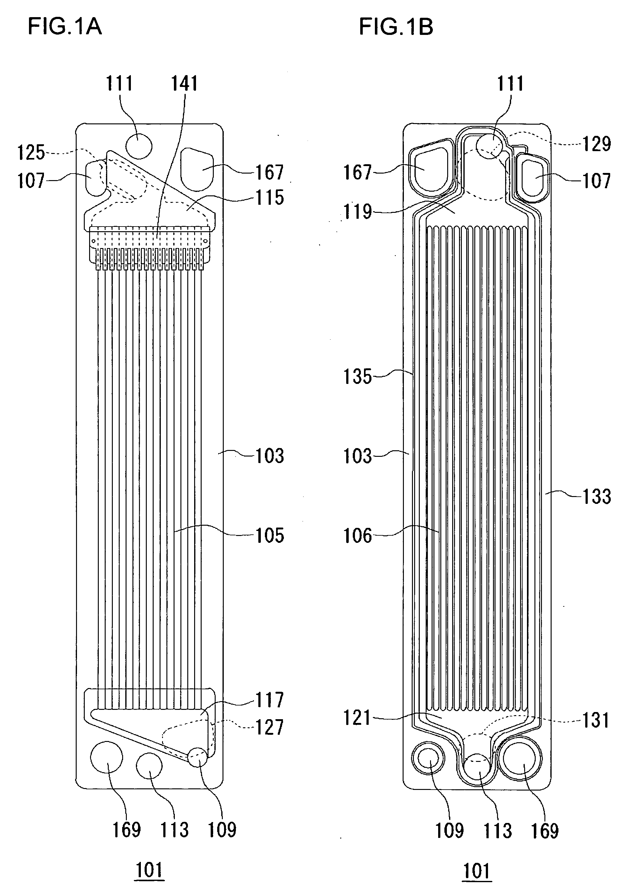
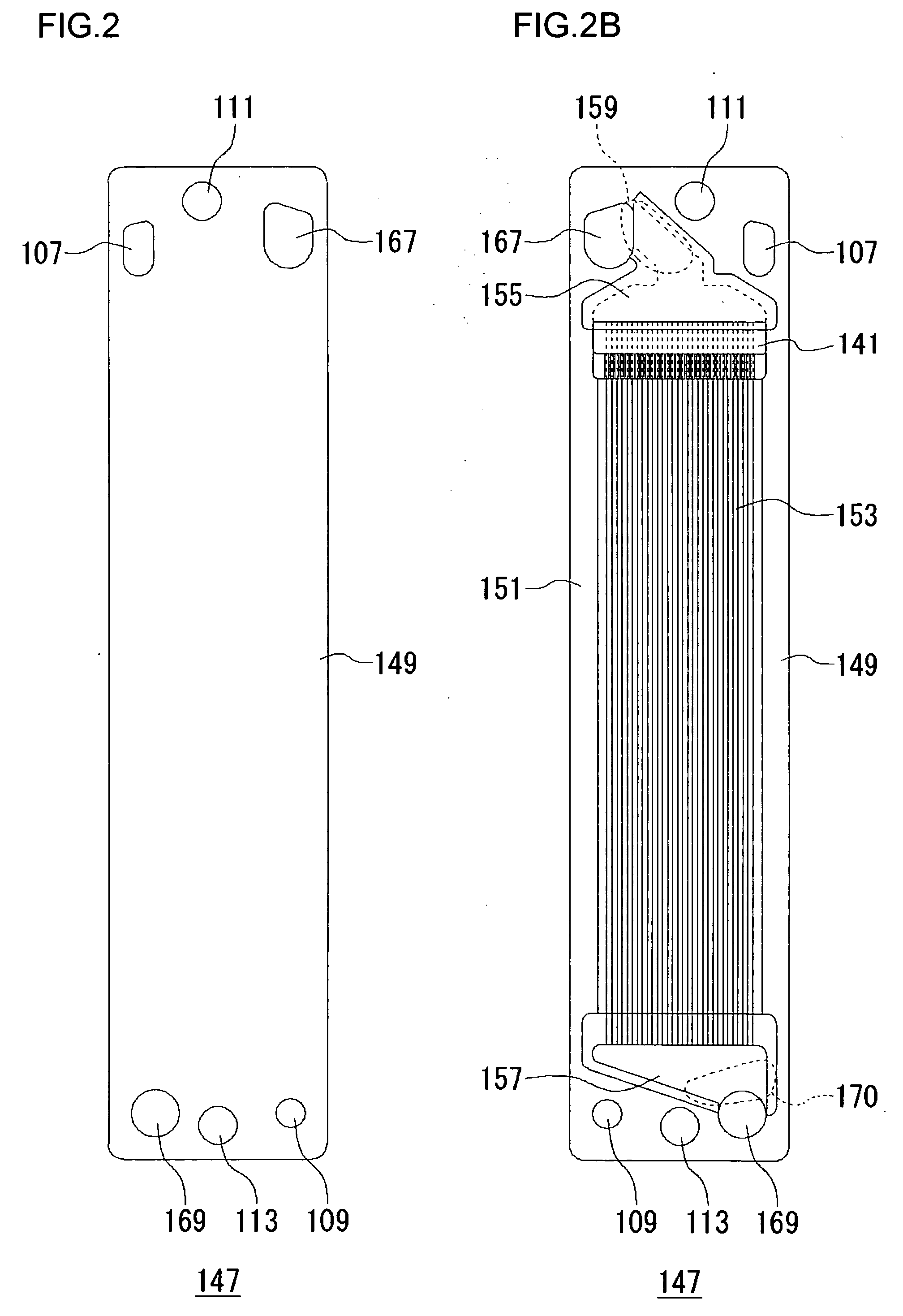
[0036] In the first embodiment, a fuel cell separator in which fuel passages are formed on a surface thereof so as to be substantially parallel with each other, and a fuel cell separator in which air passages are formed on a surface thereof so as to be substantially parallel with each other will be described. A fuel cell provided with these separators will be described. In the first embodiment, a structure in which coolant passages for a coolant such as a cooling water are formed on the back of the fuel passages will be described. Alternatively, the coolant passages may be formed on the back of the air passages. A fuel cell separator in which the coolant passages are formed on a surface thereof may be provided aside from the fuel electrode separator and the air electrode separator.

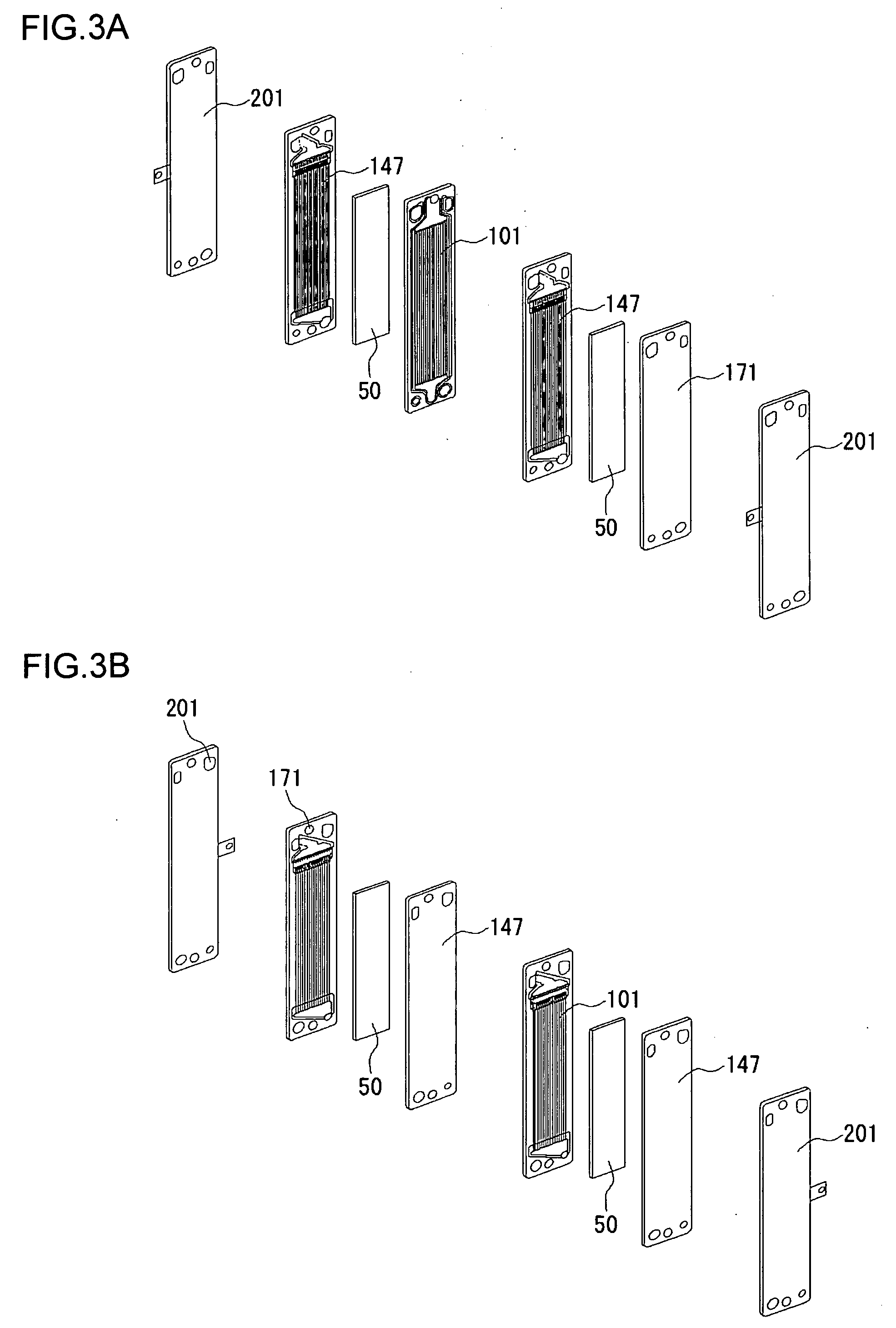
[0037]FIG. 3A is an exploded perspective view of a structure of a fuel cell stack that includes fuel cell separators according to the first embodiment. FIG. 3B is an exploded perspective view of a back si...

second embodiment

[0081]FIG. 6 shows a structure of a surface of a fuel cell separator according to the second embodiment on which surface coolant passages formed. Fuel passages are formed on the opposite surface not shown. The basic structure of the separator of FIG. 6 is the same as that of FIG. 1B. A difference is that the coolant introduction passage 129 is formed to surround the entirety of the first manifold for fuel supply 107 and the first manifold for air supply 167.

[0082]FIG. 7 shows that, in a similar configuration as the first embodiment, the first manifold for coolant supply 111 is located between the first manifold for fuel supply 107 and the first manifold for air supply 167. The distance d1 between the first manifold for coolant supply 111 and the first manifold for fuel supply 107 is smaller than the distance d2 between the first manifold for coolant supply 111 and the first manifold for air supply 167.

[0083] The same advantages as available in the first embodiment are also availab...


PUM

PropertyMeasurementUnit
temperatureaaaaaaaaaa

Abstract

A pair of separators sandwiches an electrode assembly of fuel cell including an electrolyte and a pair of electrodes provides on respective sides of the electrolyte. The separator facing a fuel electrode is provided with a coolant introduction passage on the back of a fuel introduction passage and a second manifold for fuel supply.

Description

BACKGROUND OF THE INVENTION [0001] 1. Field of the Invention [0002] The present invention relates to a fuel cell and a separator for a fuel cell. [0003] 2. Description of the Related Art [0004] Recently, fuel cells are a focus of attention due to its high energy conversion efficiency and absence of hazardous substance in an outcome of electricity generation. A polymer electrolyte fuel cell, operating in a temperature of 100° C. or lower, is known as one type of fuel cell. [0005] A polymer electrolyte fuel cell is an apparatus having a basic structure in which a solid polymer electrolyte membrane is provided between a fuel electrode and an air electrode. A fuel gas containing hydrogen is supplied to the fuel electrode and an oxidizing gas containing oxygen is supplied to the air electrode so that power is generated as a result of a reaction formulated as follows. Fuel electrode: H2—>2H++2e−  (1) Air electrode: ½O2+2H++2e−—>H2O  (2) At the fuel electrode, hydrogen contained in ...

Claims


Application Information

Patent Timeline
Patent Type & Authority Applications(United States)
IPC IPC(8): H01M2/00H01M2/02H01M2/14H01M8/04H01M8/10H01M8/12H01M8/02H01M8/18H01M8/24
CPCH01M8/0247H01M8/0258H01M8/0267H01M8/04029Y02E60/50H01M8/04119H01M8/241H01M8/248H01M8/04089H01M8/2483H01M8/2457H01M8/02
Inventor YOSHIMOTO, YASUNORIIZAKI, HIROKAZUHAMADA, AKIRA
Owner SANYO ELECTRIC CO LTD
Why Eureka
Try Eureka