Sealed cell having non-resealable safety valve

a safety valve and sealant technology, applied in the direction of cell components, non-aqueous electrolyte cells, non-aqueous electrolyte accumulators, etc., can solve the problems of variance in the pressure at which the thin portion is broken, the risk of cell burst, and the insufficient concentration of internal pressure relative to the internal pressure, so as to reduce the thickness of the valve structure, prevent damage, and minimize the effect of impact resistan

Active Publication Date: 2005-05-26
SANYO ELECTRIC CO LTD
View PDF10 Cites 18 Cited by
  • Summary
  • Abstract
  • Description
  • Claims
  • Application Information

AI Technical Summary

Benefits of technology

[0022] When pressure is applied from within the cell to the sealing plate, the deformational stress relative to the internal pressure is concentrated on the periphery of the dome. The stress is more potent with a dome protruding toward the interior of the cell than toward the exterior thereof. According to a structure of the present invention, the dome protrudes toward the interior of the cell and a break groove is formed at the periphery of the dome, as described above, and hence a strong shearing force is applied to the break groove. This renders the operating pressure and the breakage of the break groove closely related, reliably breaking the break groove as soon as the operating pressure reaches or exceeds a predetermined value. The close relationship between the operating pressure and the break groove enables a thicker valve structure at the break groove than a conventional valve for the same operating pressure. A thick valve structure at the break groove minimizes a reduction in the impact resistance resulting from the formation of the break groove. Thus, the present invention

Problems solved by technology

When the gas increases the pressure inside the cell (or internal pressure) to or over a given level, there is the risk of cell burst.
With this disclosure, however, the stress relative to the internal pressure cannot be sufficiently concentrated on the sectionally-wedge-shaped grooves, which often causes variances in the values of pressure at which the thin portion is broken.
Furthermore, the provision of the sectionally-wedge-shaped grooves renders the cell less resistant to impacts; the circular grooves can be easily damaged by the impacts of, for example, dropping, resulting in solution leakage.
Thus, this disclosure can be

Method used


Image

  • Sealed cell having non-resealable safety valve
  • Sealed cell having non-resealable safety valve
  • Sealed cell having non-resealable safety valve

Examples


example 1

[0040] An active material slurry was obtained by mixing 90 parts by mass of a positive electrode active material made of LiCoO2, 5 parts by mass of a conductivity enhancer made of carbon black, 5 parts by mass of a binder made of polyvinylidene fluoride, and a solvent made of N-methyl-2-pyrrolidone (NMP). This slurry was applied on both surfaces of a positive current collector made of an aluminum foil, and the solvent was dried. The resulting electrode plate was then rolled with a roller to a predetermined thickness and cut to a predetermined width and length. Further, a positive current collector tab made of an aluminum alloy was welded to the electrode plate.

[0041] Concurrently with the above step, an negative electrode active material slurry was prepared by mixing 95 parts by mass of a negative electrode active material made of powdered graphite, 5 parts by mass of a binder made of polyvinylidene fluoride, and a solvent made of N-methyl-2-pyrrolidone (NMP). This slurry was appli...

example 2

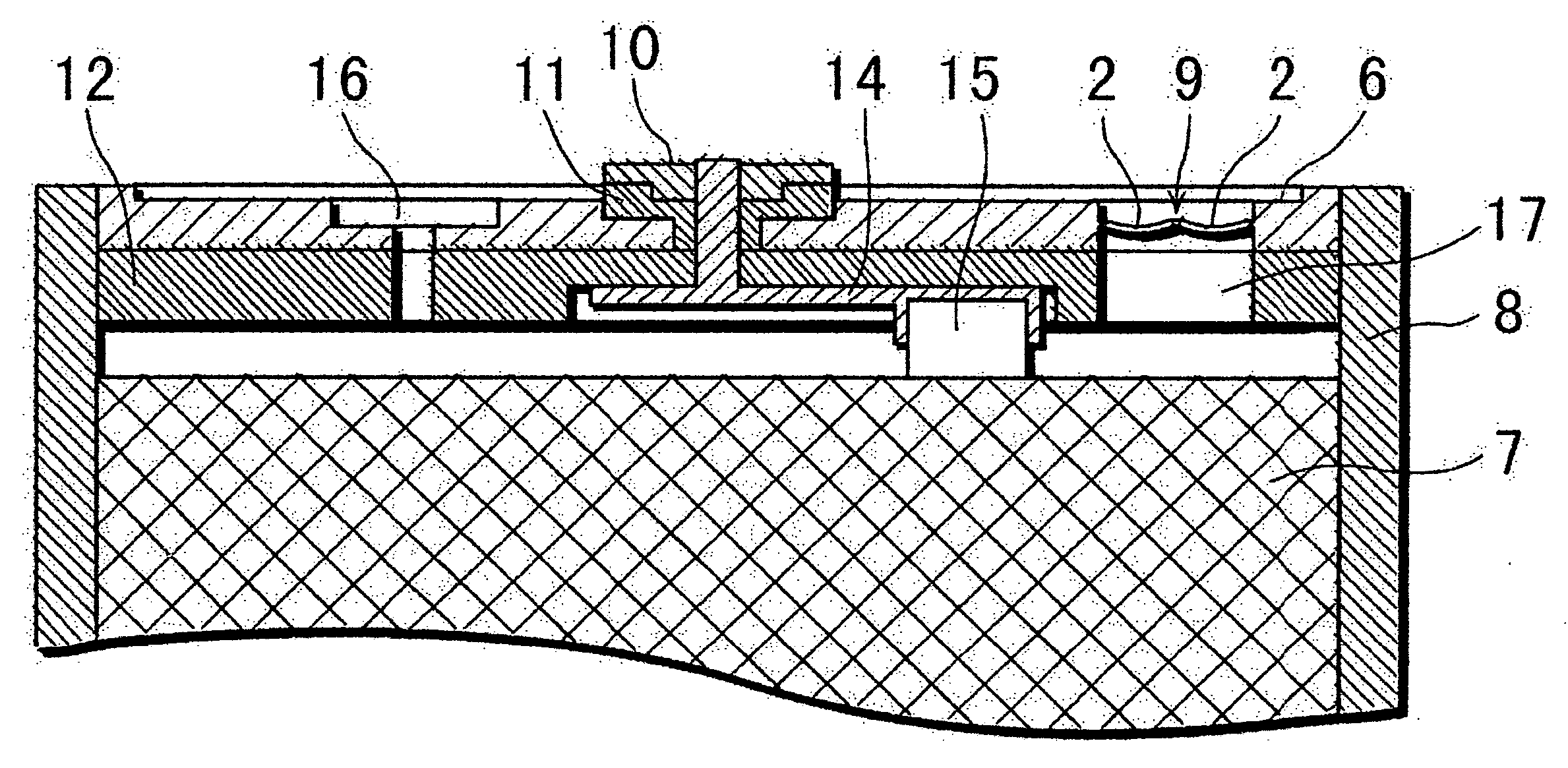
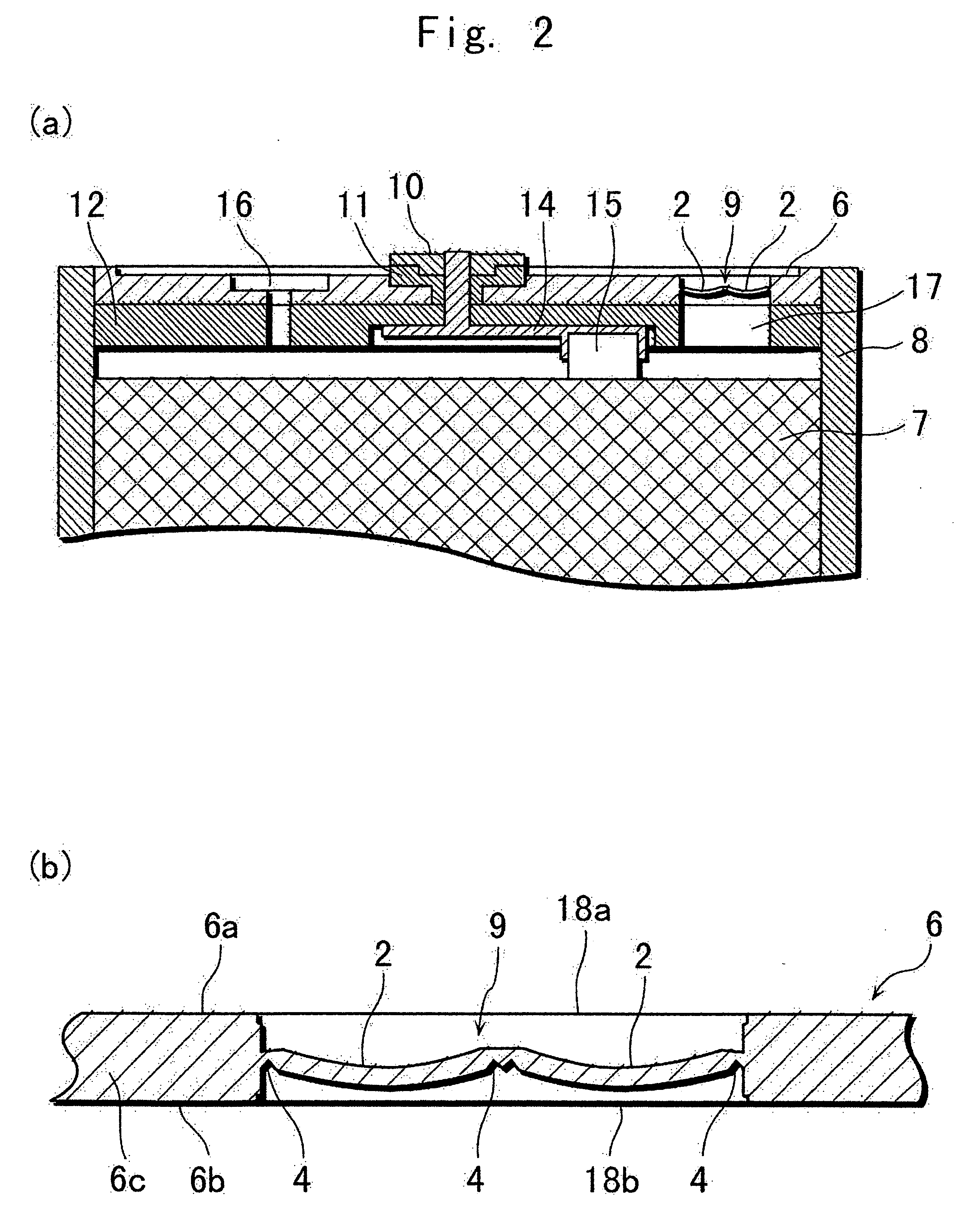
[0046] A cell according to Example 2 was prepared in the same manner as that in Example 1 except that the thickness of the valve structure 9 at each of the break grooves 4 was made 45 μm.


PUM


Abstract

A sealed cell having a safety mechanism is provided. The safety mechanism has a non-resealable valve structure formed in a sealing plate that seals the cell. The valve structure is broken as soon as the internal pressure reaches or exceeds a predetermined value so as to permit the internal gas to be released outside. The valve structure has at least one dome protruding toward the interior of the cell, which in turn has at the periphery thereof a break groove for facilitating the breakage of the valve structure. This makes the valve structure highly responsive to the internal pressure and causes to form a break-opened orifice of a sufficient area at the time of operation in response to the increased internal pressure. The valve structure is not unnecessarily broken by the impacts of, for example, dropping. As a result, the safety of the sealed cell is significantly improved.

Description

BACKGROUND OF THE INVENTION [0001] 1) Field of the Invention [0002] The present invention relates to sealed cells having non-resealable safety valves. [0003] 2) Description of the Related Art [0004] In recent years, there has been a rapid reduction in the size and weight of mobile information terminals such as mobile telephones, notebook personal computers, and PDAs (Personal Digital Assistants). Higher capacity and higher energy density are required of cells and batteries serving as the driving power sources of such terminals. Non-aqueous electrolyte secondary cells such as lithium ion secondary cells have high energy density and high capacity, and as such are widely used as the driving power sources for the terminals. Especially popular among these are square or rectangular lithium ion secondary cells for their easy mountability in the devices. [0005] When the lithium ion secondary cells, such as lithium ion secondary cells, are exposed to atmospheres of high temperature or unusua...

Claims


Application Information

Patent Timeline
IPC IPC(8): H01M2/02H01M2/12H01M6/14
CPCH01M2/0217H01M10/0525H01M6/14H01M2/1241Y02E60/10H01M50/103H01M50/3425H01M10/05
Inventor MARUBAYASHI, HIRONORIMORISHITA, TAKUMAYOSHIDA, SATOSHIKASHIMURA, RYO
Owner SANYO ELECTRIC CO LTD
Why Eureka
Try Eureka