Lithium cell and method for manufacturing the same

a technology of lithium cells and lithium batteries, applied in the field of lithium cells, can solve the problems of deformation or breakage of thin lithium foils, inability to reliably maintain adherent contact for a long time, and the lithium foil and the metallic current collection plate do not readily adhere to each other, etc., to achieve stable adherence, enhance the effect of adhesion contact, and good adhesion conta

Inactive Publication Date: 2005-05-26
NGK SPARK PLUG CO LTD
View PDF4 Cites 12 Cited by
  • Summary
  • Abstract
  • Description
  • Claims
  • Application Information

AI Technical Summary

Benefits of technology

[0006] A first advantage of the present invention is a lithium cell having good adherent contact between lithium foil and a metallic current-collecting plate and exhibiting stable adherence over a long period of time.
[0007] A second advantage of the invention is a method for manufacturing a lithium cell that enhances adherent contact between the lithium foil and the metallic current-collecting plate.
[0008] In accordance with the present invention, there is provided a lithium cell comprising a first current-collecting plate made of metal and serving as an anode; a second current-collecting plate serving as a cathode and facing the first current-collecting plate; and lithium foil or lithium alloy foil serving as an anode active substance and disposed in direct contact with a main surface of the first current-collecting plate, wherein the main surface of the first current-collecting plate in direct contact with the lithium foil or the lithium alloy foil is roughened by laser machining.
[0009] In accordance with another aspect of the present invention, there is provided a lithium cell comprising a separator; an anode active substance and a cathode active substance separated from each other by the separator; a pair of frame sheet members bonded together, one frame sheet member surrounding the anode active substance on one side of the separator, and the other frame sheet member surrounding the cathode active substance on the other side of the separator; and first and second metallic current-collecting plates fixed to the corresponding frame sheet members, the first metallic current-collecting plate and the separator holding the anode active substance therebetween, and the second metallic current-collecting plate and the separator holding the cathode active substance therebetween. In the lithium cell, the anode active substance is lithium foil or lithium alloy foil; and craterlike spots each comprising a rim and a depression are formed on the first metallic current-collecting plate in a region in contact with the lithium foil or the lithium alloy foil. Preferably, the craterlike sports are formed by means of laser machining.
[0010] In accordance with another aspect of the present invention, there is provided the surface of the metallic current-collecting plate serving as an anode is roughened. The resultant micro-irregularities bite into the soft lithium foil or lithium alloy foil to thereby yield an anchor effect, so that strong adherent contact therebetween can be maintained over a long period of time. Also, the contact area between the metallic current-collecting plate and the lithium foil or the lithium alloy foil increases, thereby lowering contact resistance.
[0011] In accordance with yet another aspect of the present invention, there is provided a method for manufacturing a lithium cell having a platelike shape and using lithium foil or lithium alloy foil as an anode active substance. The method comprises the steps of roughening the main surface of a metallic current-collecting plate associated with an anode by irradiating the main surface with a laser beam; and forcing the lithium foil or the lithium alloy foil to closely adhere to the roughened main surface.

Problems solved by technology

However, the lithium foil and the metallic current-collecting plate do not readily adhere to each other.
Application of a large force to the thin lithium foil could result in deformation or breakage of the thin lithium foil.
Lithium foil and a metallic current-collecting plate joined by merely pressing the lithium foil against the metallic current-collecting plate with strong force cannot be expected to reliably maintain adherent contact for a long period of time.
Introduction of special manufacturing equipment dedicated to the purpose of attaching the lithium foil to the metallic current-collecting plate is not a wise choice, from the viewpoint of manufacturing cost.
Mismatch between material for the metallic current-collecting plate and a roughening method may fail to properly roughen the surface of the metallic current-collecting plate or may completely fail to roughen the surface.

Method used


Image

  • Lithium cell and method for manufacturing the same
  • Lithium cell and method for manufacturing the same
  • Lithium cell and method for manufacturing the same

Examples


examples

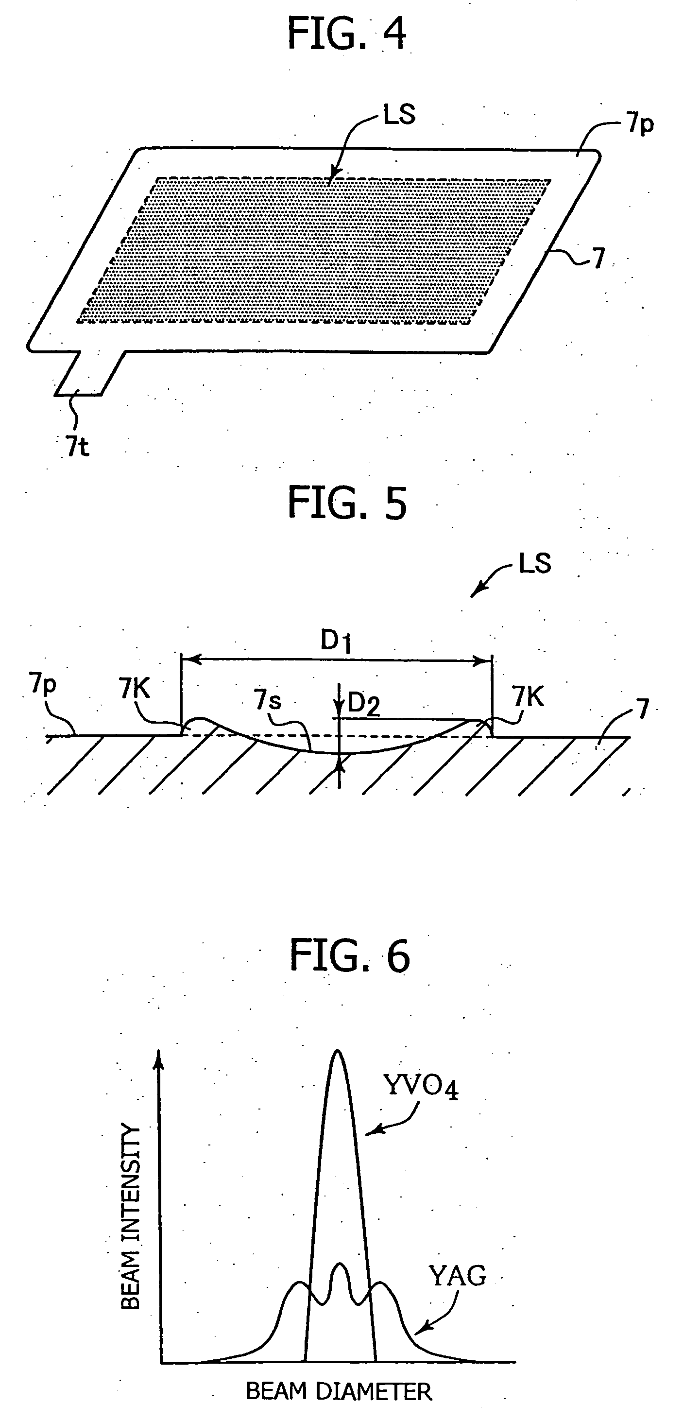
[0042] In order to confirm the effect of the present invention, the following experiments were conducted. First, a stainless steel plate (SUS304) having a thickness of 30 μm was prepared as an anodic current-collecting plate. The surface roughness of the stainless steel plate was measured. Subsequently, the surface of the stainless steel plate was roughened by use of a YVO4 laser marker (MD-V9600, product of Keyence Corp.) under the following conditions: printing speed 4,000 mm / sec; frequency 20 KHz; laser output 3W. The roughened surface was measured for roughness. FIGS. 9A and 9B shows measured surface roughness profiles.

[0043]FIG. 9A shows the surface roughness profile of the surface-roughened stainless steel plate as measured in a diametral direction of a laser-machined spot. The horizontal axis represents length in a planar direction, and the vertical axis represents length in the direction of thickness. From the profile of FIG. 9A, arithmetical mean roughness Ra=0.192 μm, and...


PUM

PropertyMeasurementUnit
diameteraaaaaaaaaa
heightaaaaaaaaaa
thicknessaaaaaaaaaa

Abstract

In a lithium cell using lithium foil or lithium alloy foil as an anode active substance, the main surface of an anodic current-collecting plate in direct contact with the lithium foil or the lithium alloy foil is roughened by laser machining.

Description

FIELD OF THE INVENTION [0001] The present invention relates to a lithium cell and a method for manufacturing the lithium cell. BACKGROUND OF THE INVENTION [0002] Conventionally, thin-plate-like lithium cells have been used as memory backup power supplies for IC cards and various pieces of electronic equipment. Such a lithium cell uses lithium foil as an anode active substance, and a transition metal oxide, such as manganese dioxide, as a cathode active substance. The lithium foil and a composite material including manganese dioxide are separated from each other by a separator while being sandwiched between two metallic current-collecting plates. [0003] In such a lithium cell, tightly-adherent contact between the lithium foil and the metallic current-collecting plate is desirable from the viewpoint of reduction in internal resistance of the cell. However, the lithium foil and the metallic current-collecting plate do not readily adhere to each other. Various attempts have been made to...

Claims


Application Information

Patent Timeline
Patent Type & Authority Applications(United States)
IPC IPC(8): H01M4/02H01M4/06H01M4/38H01M4/66H01M4/40H01M4/64H01M6/16H01M10/28
CPCH01M4/134H01M4/1395H01M4/38H01M4/382H01M4/405Y10T29/10H01M4/669H01M10/052H01M2004/021H01M2004/027Y02E60/122H01M4/64Y02E60/10Y02P70/50
Inventor GOTO, TOMOHISAMATSUMOTO, HIROSHIHARADA, SADAMITSUSUZUKA, JUNICHI
Owner NGK SPARK PLUG CO LTD
Why Eureka
Try Eureka