
Superconductive filter module, superconductive filter assembly and heat insulating type coaxial cable

a filter module and superconductive technology, applied in the direction of superconductors/hyperconductors, waveguide devices, conductive materials, etc., can solve the problems of inability to obtain desired filtering characteristics, unstable bonding state, excessive power loss in the pass band, etc., to achieve the effect of suppressing heat flow

Inactive Publication Date: 2005-05-26
FUJITSU LTD
View PDF10 Cites 7 Cited by
  • Summary
  • Abstract
  • Description
  • Claims
  • Application Information

AI Technical Summary

Benefits of technology

The present invention provides a superconductive filter module that includes a vacuum heat insulating vessel, a superconductive filter assembly, a cooling medium, a signal input cable, a signal output cable, and a heat insulating portion. The superconductive filter assembly includes a columnar resonating member attached to the inner wall of the filter housing and a center frequency adjusting member for adjusting the coupling capacity between the resonating member and the other end of the columnar resonating member. The filter housing has a heat insulating portion for insulating heat conduction. The cooling medium is provided to cool the superconductive filter assembly. The signal input and output cables have heat insulating portions. The center frequency adjusting member and bandwidth adjusting member can adjust the filtering frequencies. The ordinary conductive material or metal plating can be used for the superconductive material. The heat insulating portions can be provided at the signal coupling units. The signal input and output cables can be heat insulating coaxial cables. The external conductor can be coated with metal plating or have a heat insulating portion. The invention provides a more efficient and effective filter module for filtering radio signals.

Problems solved by technology

However, if the filter is composed of an ordinary conductive metal, the power loss in the pass band becomes excessively large.
Thus, the bonding portions 55a and 55b will suffer from damage, for example, under low temperature conditions such as of 70K, and contact at the bonding portion becomes unsatisfactory, with the result that the bonding state becomes unstable.
This means that a desired filtering characteristic cannot be obtained.
In this case, the total amount of heat conducted from the outside to the refrigerator will far exceed the permissible amount of heat [several W (watt)] flowing into the refrigerator, with the result that the superconductive filter 50 cannot be maintained in the superconductive state satisfactorily (i.e., the loss becomes large).
Thus, this filter is applicable to receiving side of radio communication equipment (e.g., abase station) but not applicable to the transmission side of the same in which power withstand performance of several tens to several hundreds or more is required.

Method used


Image

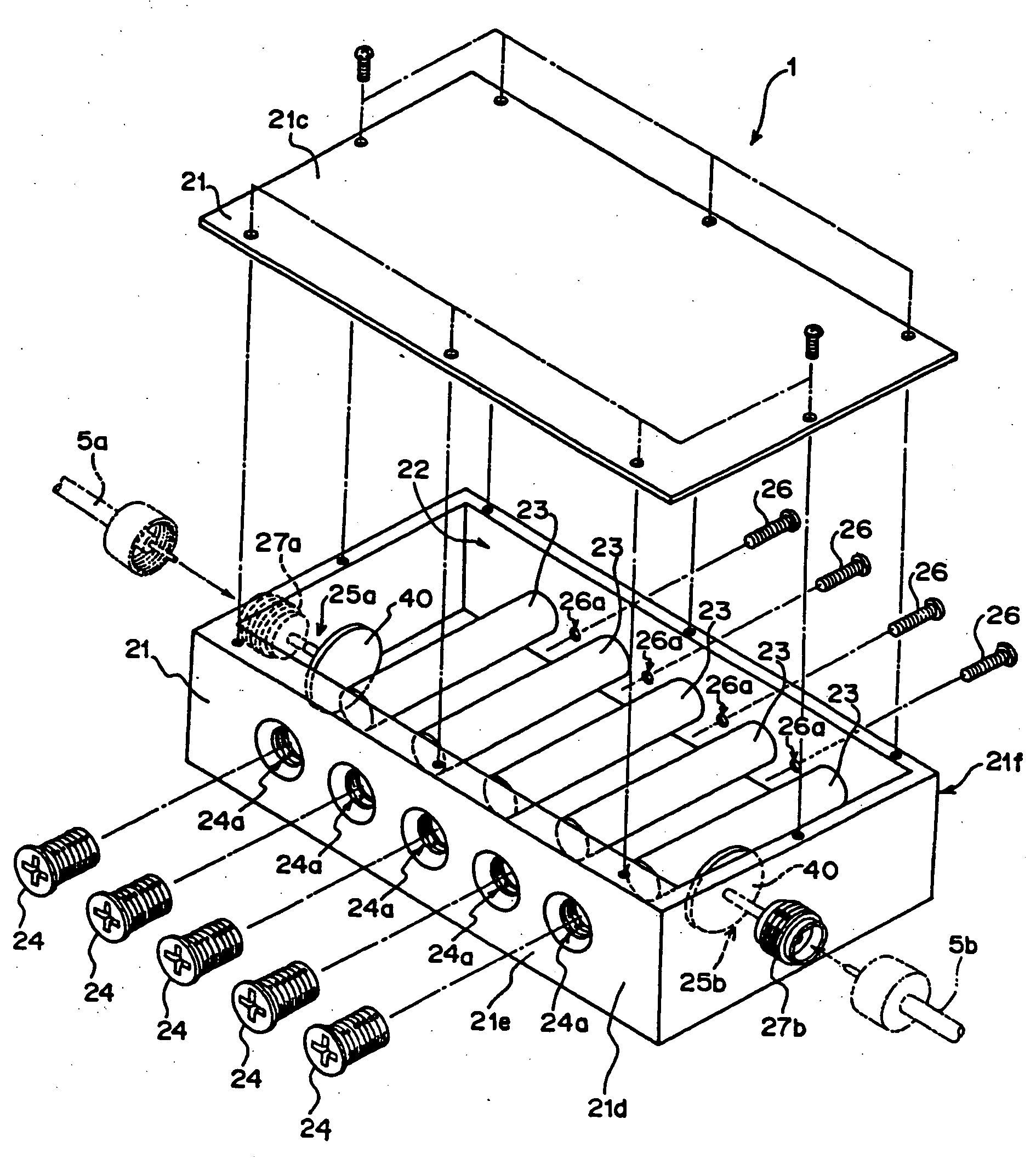
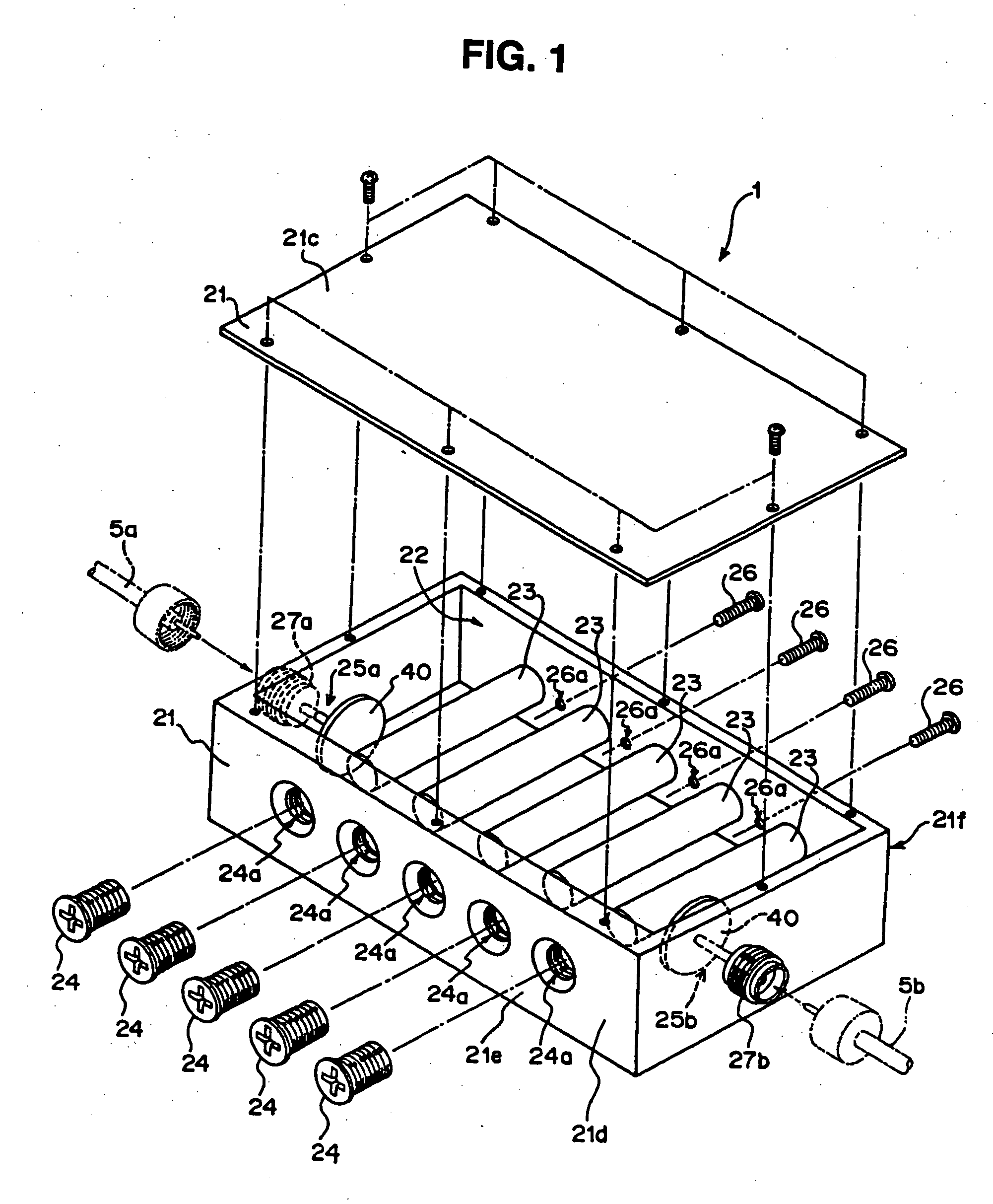
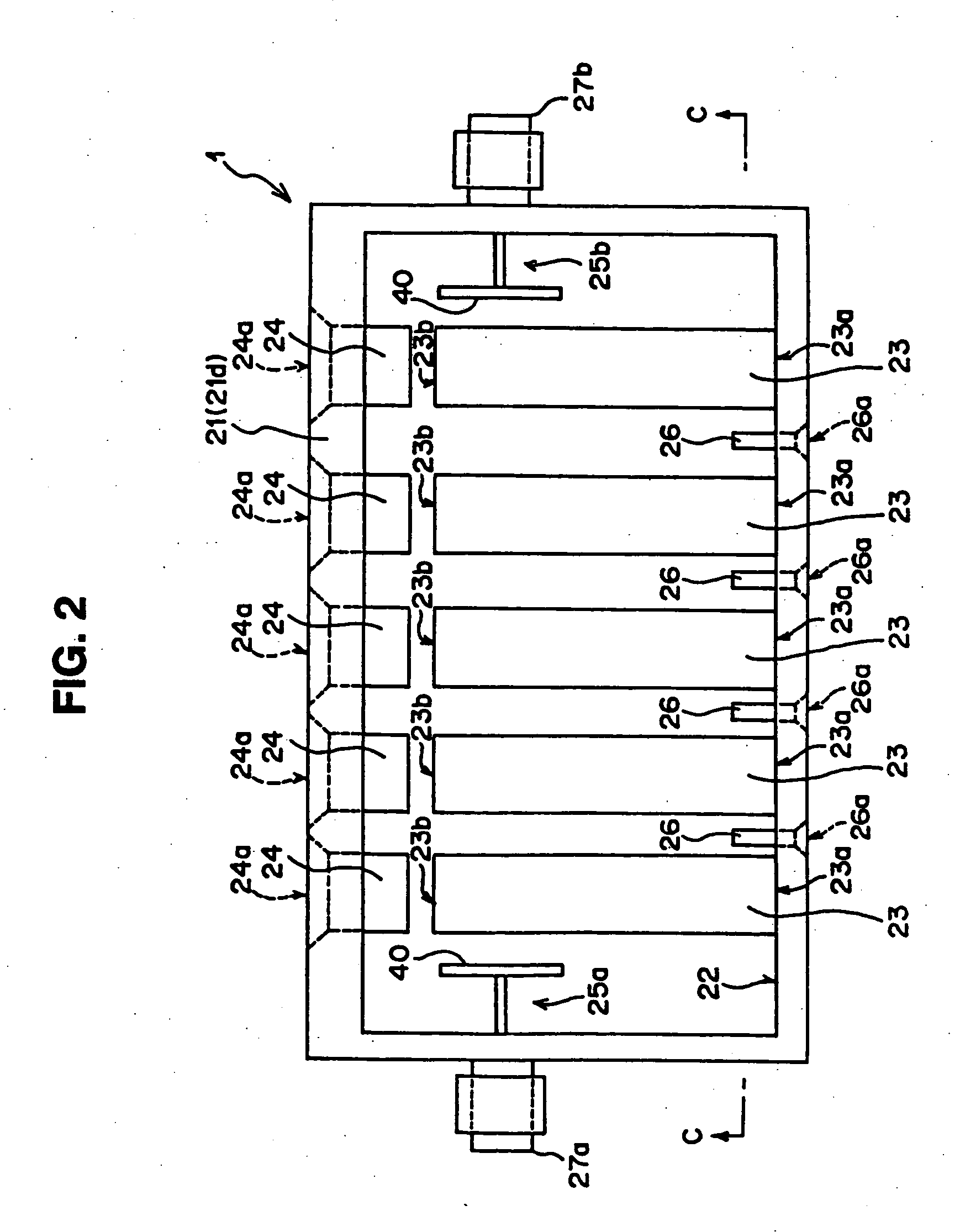
  • Superconductive filter module, superconductive filter assembly and heat insulating type coaxial cable
  • Superconductive filter module, superconductive filter assembly and heat insulating type coaxial cable
  • Superconductive filter module, superconductive filter assembly and heat insulating type coaxial cable

Examples


first modification

[0138] (C1) Description of First Modification

[0139]FIG. 8 is a perspective view schematically showing a first modification of the above-described coaxial cable 5a (5b). As shown in FIG. 8, the coaxial cable 5a (5b) has an external conductor 113 a part of which (e.g., the peripheral width of about 1 mm) is removed to expose the dielectric body. A capacitor (electrostatic capacity element) 114 having an electrostatic capacity [e.g., in the present embodiment, 10 pF (picofarads)] corresponding to the frequency of the transmitted microwave is connected between the separated external conductor 113. In FIG. 8, reference numeral 111 represents the center conductor of the coaxial cable 5 (5b), and 112 dielectric body (insulating member) coating the center conductor 111.

[0140] That is, the coaxial cable 5a (5b) of the first modification is arranged to include the external conductor 113 coating the dielectric body 112 so that a part of the periphery of the dielectric body is exposed, and the...

fourth embodiment

[0160] According to the arrangement of the coaxial cable 5a (5b) as the fifth modification, since the heat conducting path is further elongated as compared with that in the arrangement of the fourth embodiment described above, the heat insulating effect becomes more effective.

[0161] Also in this case, the material of the copper plate sheet 153 may be replaced with any metal such as silver, gold, nickel or the like. Furthermore, it is needless to say that the width, the interline gap, the pitch or the like of the meander-form may take any value different from the above value.

[0162] The following table shows a result of simulation illustrating how the heat amount conducted through the coaxial cable can be suppressed owing to the heat insulating processing. The condition (environment) of the simulation is such that, for example, in FIG. 6, the temperature of the surrounding atmosphere is 300K, the temperature of the cold head 3 is 70K, and these temperatures are made constant. The len...


PUM

PropertyMeasurementUnit
temperatureaaaaaaaaaa
diameteraaaaaaaaaa
center frequencyaaaaaaaaaa

Abstract

The present invention relates to superconductive filter technology. According to the arrangement of the superconductive filter (1), a columnar resonating member (23) having a superconductive material formed on the surface thereof is attached at one of its ends thereof to an inner wall (22) of a filter housing (21) so that a space is interposed between the columnar resonating member and each of connectors (27a, 27b) which are connectable to a signal input / output cables (5a, 5b), respectively. According to this arrangement, heat conduction from the outside can be suppressed as far as possible, and the superconductive condition can be created with stability, with the result that a stable filtering characteristic can be created. Further, the superconductive filter according to the present invention will become excellent in power withstand performance, and hence even if the number of stages of filters is increased for attaining a steep cutoff characteristic, the loss deriving from the increased number of stages can be suppressed to the minimum level.

Description

TECHNICAL FIELD [0001] The present invention relates to a superconductive filter module, a superconductive filter assembly and a heat insulating type coaxial cable, and more particularly to a superconductive filter module, a superconductive filter assembly and a heat insulating type coaxial cable suitable for use with mobile communication equipment. BACKGROUND ART [0002] Recently, the number of users of mobile communication equipment are increasing rapidly, and hence there has been greater demand for more effective utilization of a limited width frequency bands. For this reason, a band-pass filter (in particular, a filter utilized on the side of a base station under a microwave band environment) is required to have a steep cutoff characteristic and a low power loss performance in the pass-band. To implement a filter having a steep cutoff characteristic under a microwave band environment, the number of filter stages shall be increased. However, if the filter is composed of an ordinar...

Claims


Application Information

Patent Timeline
Patent Type & Authority Applications(United States)
IPC IPC(8): H01B1/00H01P1/205H01P7/04
CPCH01P1/202H01P1/205H01P1/30Y10S505/701Y10S505/70Y10S505/866H01P7/04
Inventor KAI, MANABUYAMANAKA, KAZUNORIHASEGAWA, TSUYOSHIMANIWA, TORU
Owner FUJITSU LTD
Learn More