Unlock instant, AI-driven research and patent intelligence for your innovation.

Motor vehicle state detecting system

a technology for motor vehicles and state detection, applied in the field of motor vehicle state detection apparatus or system, can solve the problems of rapid change of motor vehicle behavior, unstable state of motor vehicle, and inability to detect the state of the motor vehicle, and achieve the effect of high accuracy and reliability

Active Publication Date: 2005-05-26
MITSUBISHI ELECTRIC CORP
View PDF1 Cites 5 Cited by
  • Summary
  • Abstract
  • Description
  • Claims
  • Application Information

AI Technical Summary

Benefits of technology

[0018] In the light of the state of the art described above, it is an object of the present invention to provide a motor vehicle state detecting system which is capable of detecting with high accuracy and reliability the unstable state of behavior of the motor vehicle or the prognostic sign thereof by detecting actual parameter values generated actually in the motor vehicle even in the case where the grip force (friction force) of tire is lowered.
[0024] By virtue of the arrangements of the motor vehicle state detecting system described above, the unstable state of the motor vehicle or prognostic sign thereof can be detected with high accuracy and reliability even when the grip force of tire becomes lowered.

Problems solved by technology

In general, in the state in which the anti-skid braking system is being actuated, there is a possibility of the behavior of the motor vehicle changing rapidly.
Further, when the quick steering operation has been conducted, there is a possibility that the motor vehicle has already been in an unstable state with the behavior of the motor vehicle changing rapidly.
However, in a slippery road surface condition such as typified by a snow-covered road, there may occur such situation that the motor-vehicle falls into a spinning state even when the steering operation is performed slowly without effectuating the braking operation.
As is apparent from the foregoing, the conventional motor vehicle state detecting system is so arranged as to detect the unstable state of the motor vehicle on the basis of operation of the anti-skid braking system and quick manipulation of the steering wheel (steering handle) Thus, with the conventional motor vehicle state detecting system, it is difficult or impossible to detect with accuracy the unstable state of the motor vehicle on the slippery road surface condition such as the snow-covered road condition or the like, giving rise to a problem.

Method used


Image

  • Motor vehicle state detecting system
  • Motor vehicle state detecting system
  • Motor vehicle state detecting system

Examples


embodiment 1

[0090]FIG. 1 is a block diagram showing generally and schematically a system configuration of the motor vehicle state detecting system according to a first embodiment of the present invention.

[0091] Referring to FIG. 1, reference numeral 1 denotes a side slip angle measuring unit which constitutes a first detecting means for detecting an actual side slip angle β of a vehicle body or tire of the motor vehicle as an actual measured value of a first parameter.

[0092] A normative or normal alignment torque arithmetic unit 2 which constitutes a normal value arithmetic means includes a torque / slip-angle ratio setting means (not shown) for setting a torque / slip-angle ratio (=gain Ka) and serves for arithmetically determining a normal alignment torque To on the basis of the actual side slip angle β and the torque / slip-angle ratio (gain Ka).

[0093] The torque / slip-angle ratio setting means incorporated in the normal alignment torque arithmetic unit 2 serves to set a ratio of the alignment t...

embodiment 2

[0121] In the motor vehicle state detecting system according to the first embodiment of the invention, the normal alignment torque To is arithmetically determined by using the torque / slip-angle ratio (gain Ka) to thereby make decision that the motor vehicle is in the unstable state when the alignment torque deviation ΔT of the actual alignment torque Ta from the normal alignment torque To is greater than the predetermined value α1 inclusive thereof. By contrast, in the motor vehicle state detecting system according to a second embodiment of the present invention, such arrangement is adopted that the rate of change (hereinafter also referred to simply as the change rate) of the actual alignment torque Ta for the side slip angle β is arithmetically determined or alternatively measured to thereby make decision that the motor vehicle is in the unstable state when the torque / slip-angle change rate (i.e., change rate of the actual alignment torque relative to the actual side slip angle) d...

embodiment 3

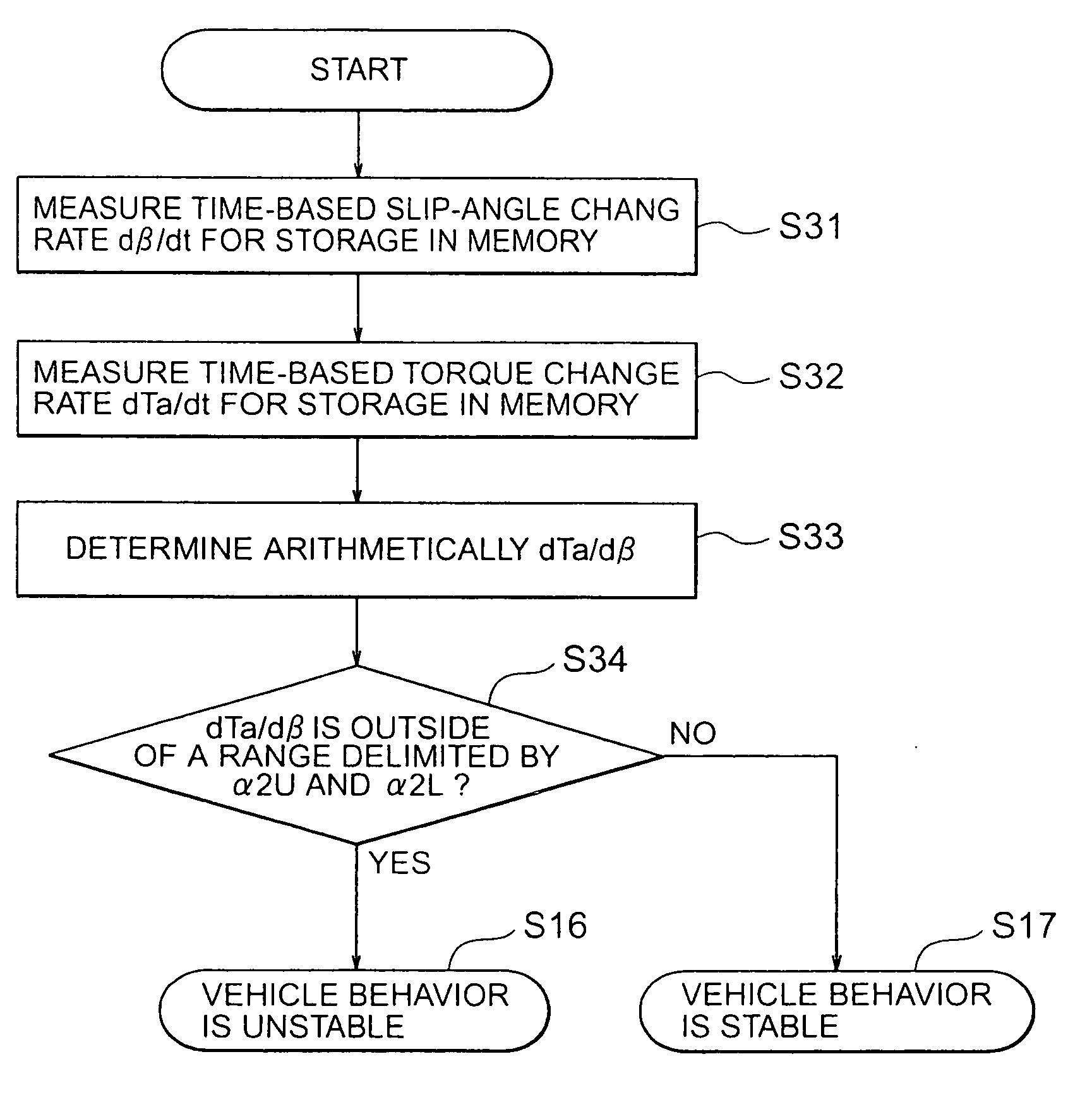
[0135] In the motor vehicle state detecting system according to the second embodiment of the invention, the torque / slip-angle change rate measuring unit 6 is employed for making available the torque / slip-angle change rate dTa / dβ. By contrast, in the case of the motor vehicle state detecting system according to a third embodiment of the present invention, time-based change rates of the actual side slip angle β and the actual alignment torque Ta, respectively, are measured and subjected to division processing for thereby determining the torque / slip-angle change rate dTa / dβ.

[0136]FIG. 6 is a block diagram showing generally and schematically a major portion of the motor vehicle state detecting system according to the third embodiment of the invention in which the torque / slip-angle change rate dTa / dβ is determined on the basis of the time-based change rates of the actual side slip angle β and the actual alignment torque Ta, respectively.

[0137] Referring to FIG. 6, the arithmetic means ...


PUM


Abstract

System for detecting stability / instability of behavior of a motor vehicle upon occurrence of tire slip or lock. State of the motor vehicle is determined on the basis of an alignment torque (Ta) applied from a road and a side slip angle (β). By taking advantage of such torque / slip-angle characteristic that although the alignment torque is proportional to a side slip angle when the latter is small, the alignment torque becomes smaller as the side slip angle increases, a normal value is determined from a straight line slope and the side slip angle in a region where the latter is small. Unstable behavior of the motor vehicle is determined when deviation of actual measured value from the normal value increases. Further, unstable state is determined when the slope of the alignment torque for the slip angle departs significantly from that of approximate straight line slope.

Description

BACKGROUND OF THE INVENTION [0001] 1. Field of the Invention [0002] The present invention generally relates to a motor vehicle state detecting apparatus or system which is employed in conjunction with a drive recorder for a motor vehicle and / or for generation of a control start signal for the control of behavior of the motor vehicle. In particular, the invention is concerned with a motor vehicle state detecting system for detecting an unstable state of behavior of the motor vehicle or a prognostic sign thereof. More particularly, the present invention is concerned with a motor vehicle state detecting system which is capable of detecting accurately an unstable state of behavior of a motor vehicle or a prognostic sign thereof with high reliability even in the case where a grip force (friction force) of tire decreases. [0003] 2. Description of Related Art [0004] For having better understanding of the concept underlying the present invention, description will first be made of the hither...

Claims


Application Information

Patent Timeline
IPC IPC(8): B60R16/02B60W40/10B60W40/101B60W40/103B62D5/04B62D6/00B62D6/04B62D101/00B62D111/00B62D117/00B62D121/00B62D137/00G06F7/00G06F7/70G08G1/16
CPCB60T2230/02B62D6/04B62D6/005B60T2260/02
Inventor FUJIOKA, HIROSHIMATSUNAGA, TAKANORIMAEDA, TAKASHIMATSUI, TOSHINORIKURISHIGE, MASAHIKOTANAKA, HIDEYUKI
Owner MITSUBISHI ELECTRIC CORP
Features
  • R&D
  • Intellectual Property
  • Life Sciences
  • Materials
  • Tech Scout
  • Unparalleled Data Quality
  • Higher Quality Content
  • 60% Fewer Hallucinations
Learn More