Exhaust emission control device and casing structure of the control device

a technology of exhaust gas purification device and control device, which is applied in the direction of machines/engines, mechanical equipment, separation processes, etc., can solve the problems of affecting the heating of the filter, affecting the efficiency of the filter, and increasing the engine load, so as to reduce energy loss, reduce heat loss, and improve efficiency

Inactive Publication Date: 2005-06-02
IBIDEN CO LTD
View PDF10 Cites 53 Cited by
  • Summary
  • Abstract
  • Description
  • Claims
  • Application Information

AI Technical Summary

Benefits of technology

[0014] In each of the above-described embodiments, the outer peripheral surface of the filter is held in contact with the inner case. However, the clearance is defined between the inner case and the outer case. Therefore, in other words, a heat insulating air layer is ensured between the inner and outer cases. The heat transmission from the inner case to the outer case is thus hampered. This prevents the heat from escaping to the exterior of the filter such that the temperature of the filter is efficiently raised. That is, the exhaust gas purifying device reduces energy loss and thus saves costs. Further, since the heat is prevented from escaping from the outer peripheral portion of the filter, the temperature difference between the middle portion and the outer peripheral portion of the filter hardly occurs. As a result, a relatively large thermal stress, which leads to cracks damaging the filter, is avoided.
[0015] If the fluid blocking member is provided at the upstream end portion of the inner case, communication between the space including the upstream end surface of the filter and the clearance is blocked. Therefore, a relatively hot exhaust gas does not flow into the clearance in which the heat insulating air layer is formed. This structure reduces heat energy loss caused by heat transmission from the exhaust gas to the outer case. The costs are thus further saved. Further, the exhaust gas does not bypass the filter or reach the downstream side of the filter without being purified. The purifying efficiency is thus prevented from being lowered.
[0016] If the fluid blocking member is provided at the downstream end portion of the inner case, communication between the space including the downstream end surface of the filter and the clearance is blocked. This structure further reduces the heat energy loss caused by the heat transmission from the exhaust gas to the outer case. The costs are thus further saved.
[0017] If the fluid blocking member is configured by the flange, the flange serves also as a portion to which the inner case is secured. This avoids an increase in the number of the parts and complication of the structure. Further, the filter may be removed from the outer case in a state accommodated in the inner case. The replacement of the filter thus becomes relatively easy, as compared to a conventional case. As a result, maintenance is facilitated.
[0018] If a heater for regenerating the filter and heat reflector are provided, the heat of the heater is reflected by the heat reflector. The heat energy loss of the heater is thus decreased, and the filter is heated efficiently. Further, since the heat reflector is porous, the flow of the exhaust gas to the filter is not hampered.

Problems solved by technology

As the filter is used for a relatively long time, the filter collects soot (diesel particulates) from the exhaust gas.
The soot is deposited in the filter and gradually increases the engine load.
However, conventional exhaust gas purifying devices have the following problems.
The heat thus escapes to the exterior of the filter, hampering the heating of the filter.
This increases the energy needed to heat the filter to the soot ignition temperature and raises costs.
Further, if an electric heater is used as the heating means, an increased electric load is applied to the battery, which accelerates the battery consumption.
In addition, a temperature difference is caused between the middle portion of the filter and an outer peripheral portion of the filter.
In this case, the filter has a tendency to crack, which is damaging to the filter.
Moreover, in conventional devices, replacement of the filter is complicated, making it difficult to maintain the devices.

Method used


Image

  • Exhaust emission control device and casing structure of the control device
  • Exhaust emission control device and casing structure of the control device
  • Exhaust emission control device and casing structure of the control device

Examples


first embodiment

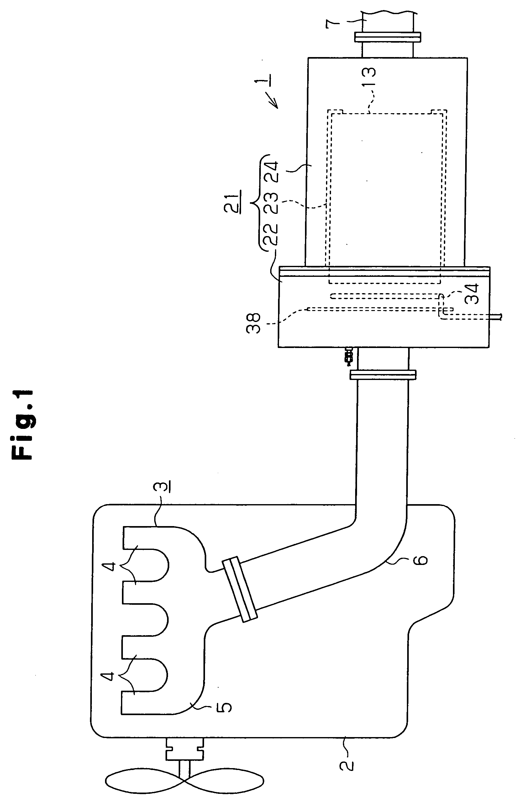
[0028] An exhaust gas purifying device 1 according to the present invention will hereafter be described with reference to FIGS. 1 to 5.

[0029] As illustrated in FIG. 1, the exhaust gas purifying device 1 purifies exhaust gas discharged by a diesel engine 2, which serves as an internal combustion engine. The diesel engine 2 includes a plurality of non-illustrated cylinders. A branch 4 of a metal exhaust manifold 3 is coupled to each of the cylinders. The branches 4 are connected to a manifold body 5. Thus, the exhaust gas sent from each of the cylinders is concentrated at one point.

[0030] A first exhaust pipe 6 and a second exhaust pipe 7, which are formed of metal, are disposed at a downstream side of the exhaust manifold 3. An upstream end of the first exhaust pipe 6 is coupled to the manifold body 5. The exhaust gas purifying device 1 is located between the first exhaust pipe 6 and the second exhaust pipe 7.

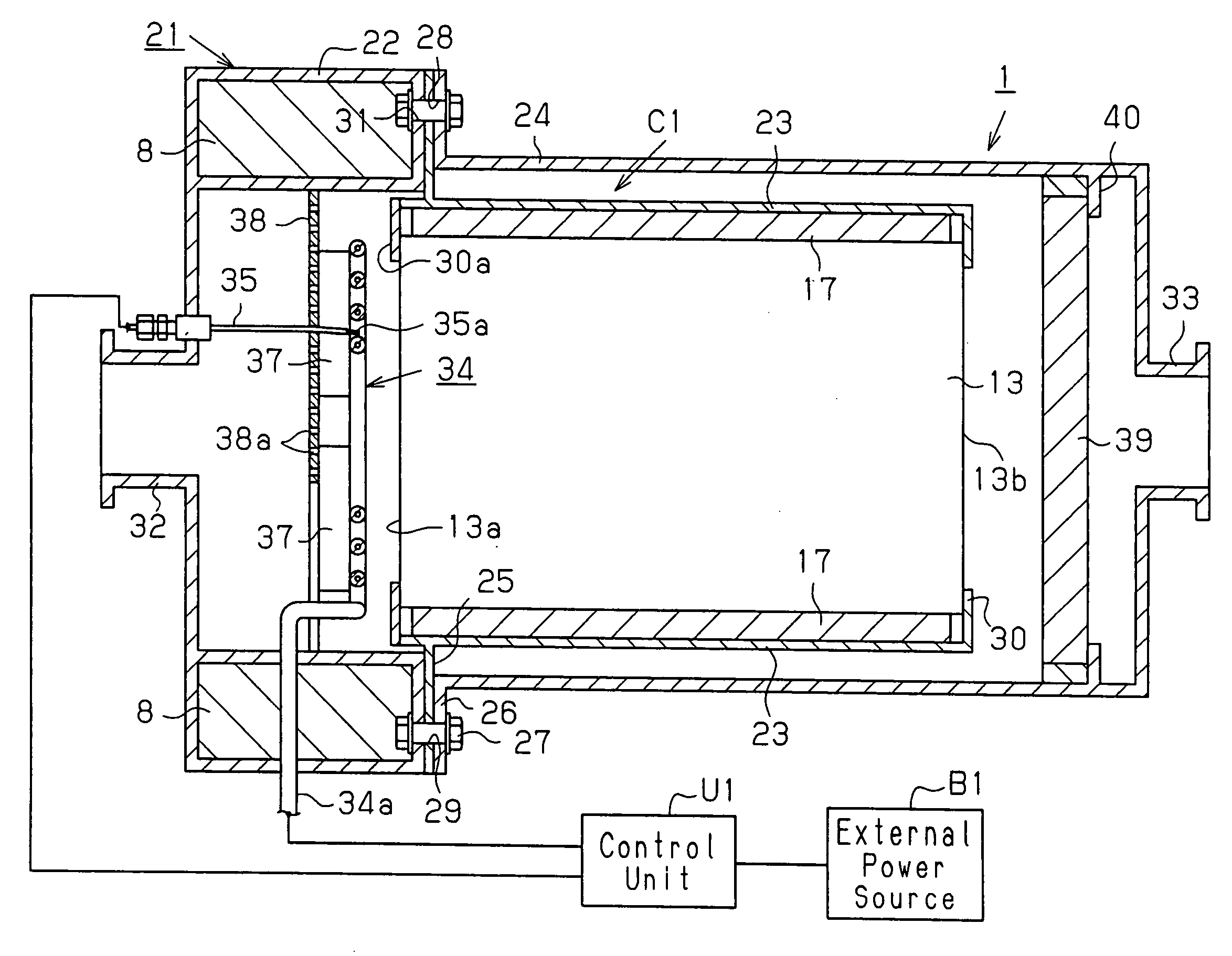
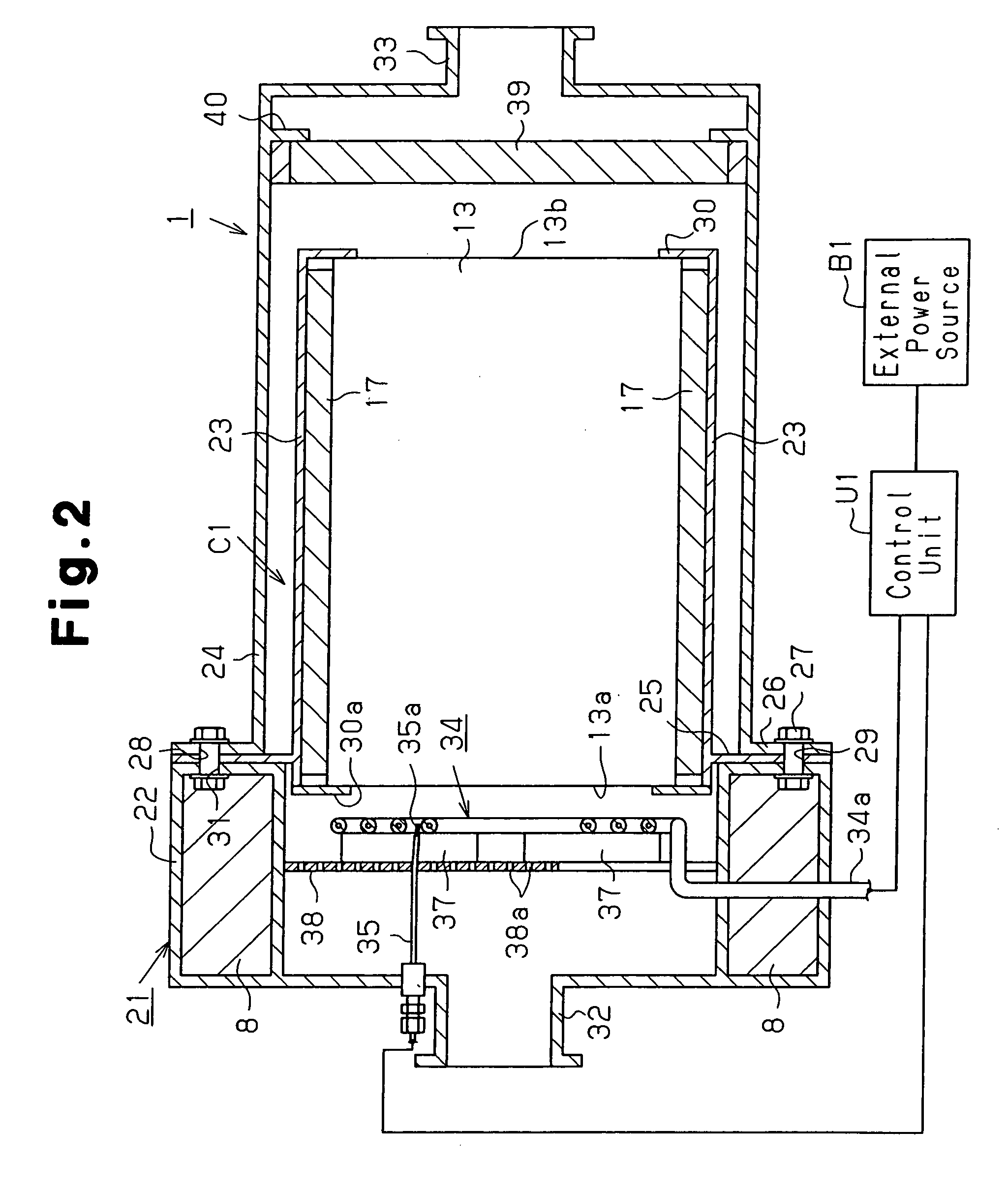
[0031] With reference to FIG. 2, the exhaust gas purifying device 1 inclu...

fourth embodiment

[0066] Also, the fourth embodiment is not provided with the punching plate 38 such that the configuration becomes simple.

[0067] In a fifth embodiment illustrated in FIG. 9, the support piece 30a, which is otherwise formed at the upstream end portion of the inner case 23, is not provided, as is clear from comparison with the first embodiment. The fifth embodiment thus has the operational effects of the first embodiment, except for that of the support piece 30a.

[0068] The exhaust gas purifying devices of the illustrated embodiments were subjected to an operational test. One cycle of the test was defined by sending exhaust gas to each of the devices, heating the filter by the heater, and supplying supporting air for burning the soot. The test included ten cycles. The test results are shown in Table 1. The longitudinal dimension of the filter 13 was 150 millimeters.

TABLE 1Up-Down-TemperatureInsulatorstreamstreamSupportPunchingDifferenceCorrosionEmbodimentDrawingBlockerBlockerStructur...


PUM

PropertyMeasurementUnit
ignition temperatureaaaaaaaaaa
temperatureaaaaaaaaaa
timeaaaaaaaaaa

Abstract

An exhaust gas purifying device includes a tubular casing arranged in exhaust passages of an internal combustion engine. A filter is held in the casing. The filter collects and burns particulates contained in the exhaust gas discharged by the internal combustion engine. The casing has a double structure including an inner case supporting an outer peripheral surface of the filter and an outer case arranged around the inner case. The inner and outer cases are spaced from each other with a clearance defined between the cases.

Description

FIELD OF THE INVENTION [0001] The present invention relates to exhaust gas purifying devices for purifying exhaust gas discharged by internal combustion engines including diesel engines and casing structures for the devices. BACKGROUND OF THE INVENTION [0002] Conventionally, a number of exhaust gas purifying devices have been proposed. The devices are configured by accommodating a ceramic honeycomb filter for purifying exhaust gas in a metal tubular casing, which is disposed in an exhaust passage of a diesel engine. As the filter is used for a relatively long time, the filter collects soot (diesel particulates) from the exhaust gas. The soot is deposited in the filter and gradually increases the engine load. If this is the case, the filter is heated to the ignition temperature of the soot (600 to 630 degrees Celsius) by a heating means such as a heater or burner. The soot is thus burned and removed such that the filter is regenerated. [0003] However, conventional exhaust gas purifyi...

Claims


Application Information

Patent Timeline
Patent Type & Authority Applications(United States)
IPC IPC(8): F01N13/08B01D46/42F01N3/02F01N3/021F01N3/022F01N3/025F01N3/027F01N13/14F01N13/18
CPCF01N3/0211F01N3/022F01N3/0222F01N3/025Y02T10/20F01N13/14F01N2260/08F01N2260/10F01N3/027Y02T10/12
Inventor KOJIMA, MASAAKI
Owner IBIDEN CO LTD
Why Eureka
Try Eureka