Refrigeration equipment

a technology of refrigerating equipment and refrigeration pipes, which is applied in the direction of refrigeration components, lighting and heating equipment, machine operation modes, etc., can solve the problems of large loss of refrigerant, complicated work for connecting such pipes, and easy reduction of refrigerating ability, so as to reduce the total number of communication pipes, reduce the enthalpy, and prevent the effect of refrigerating ability

Inactive Publication Date: 2005-06-02
DAIKIN IND LTD
View PDF0 Cites 17 Cited by
  • Summary
  • Abstract
  • Description
  • Claims
  • Application Information

AI Technical Summary

Benefits of technology

[0019] In accordance with the first invention, liquid lines for a plurality of channels in the refrigerant circuit (1E) share one liquid side communication pipe (11), and the liquid side communication pipe (11) is provided adjacent to the low-pressure gas side communication pipe (15) for a gas line of at least one channel so as to contact it in order to supercool a liquid refrigerant by a gas refrigerant. Thus, a refrigerant having lower enthalpy can be supplied to the application-side heat exchangers (41, 45, 51). For this reason, the difference in enthalpy between refrigerants at entrances / exits for the application-side heat exchangers (41, 45, 51) becomes large, and a decrease in refrigerating ability can be prevented even if pipes are long.
[0020] As liquid lines for a plurality of channels are integrated into one liquid side communication liquid pipe (11), the total number of communication pipes is reduced. Accordingly, work for connecting pipes is easily performed and the possibility of connecting wrong pipes is reduced. Namely, workability for piping is improved.
[0021] In accordance with the second invention, in the refrigerant circuit (1E) having the cold-storage / freezing-channel and the air-conditioning channel, a joined liquid refrigerant from both of the channels is supercooled by a sucked gas refrigerant for the cold-storage / freezing channel. A decrease in ability can be prevented and the workability for piping can be improved. In the case of the apparatus having the cold-storage / freezing channel and the air-conditioning channel separately, a direction that a refrigerant is circulated is fixed in the cold-storage / freezing channel and a gas line is not switched between the discharge side and the suction side. Accordingly, the low-pressure gas side communication pipe (15) for the cold-storage / freezing channel and the joined liquid side communication pipe (11) for both of the channels can be easily provided adjacent to each other. As the communication pipe (17) in a gas line for the air-conditioning channel is not provided adjacent to the liquid side communication pipe (11), it can be configured so as to perform air-cooling / air-heating by switching directions in which a refrigerant circulates.
[0022] In accordance with the third invention, there is provided the liquid injection pipe (27) for supplying a part of liquid refrigerant circulating in the refrigerant circuit (1E) to the suction sides of the compression mechanisms (2D, 2E). Thus, even if a degree of superheat of the gas refrigerant at the suction side becomes large when a liquid refrigerant is supercooled by the gas refrigerant at the suction side, performing liquid injection can prevent the degree of superheat from being excessively large in a compression process. As a result, because of structures of the first and second inventions, a refrigerating apparatus in which a decease in workability is suppressed while a decrease in ability is prevented can be reliably put to practical use.
[0023] In accordance with the fourth invention, the liquid side communication pipe (11) and the low-pressure gas side communication pipe (15) are surrounded by the heat transfer material (12). Accordingly, a liquid refrigerant can be reliably supercooled by a gas refrigerant via the heat transfer material (12). Further, a heat exchanger dedicated to supercooling of a liquid refrigerant is not required and thus the structure cannot be complicated.
[0024] In accordance with the fifth invention, the aluminum tape material (12) is wound, as a heat transfer material, around the liquid side communication pipe (11) and the low-pressure gas side communication pipe (15). Thus, supercooling of a liquid refrigerant by a low-pressure gas refrigerant can be realized by an extremely simple structure.

Problems solved by technology

Nevertheless, when the length of the pipes is extremely long, a pressure loss for the refrigerant becomes large and thus a refrigerating ability may be easily decreased.
Work for connecting such pipes is complicated and the pipes may be connected in a wrong manner.

Method used


Image

  • Refrigeration equipment
  • Refrigeration equipment
  • Refrigeration equipment

Examples


Embodiment Construction

[0037] An embodiment of the present invention will be described in detail hereinafter based on the drawings.

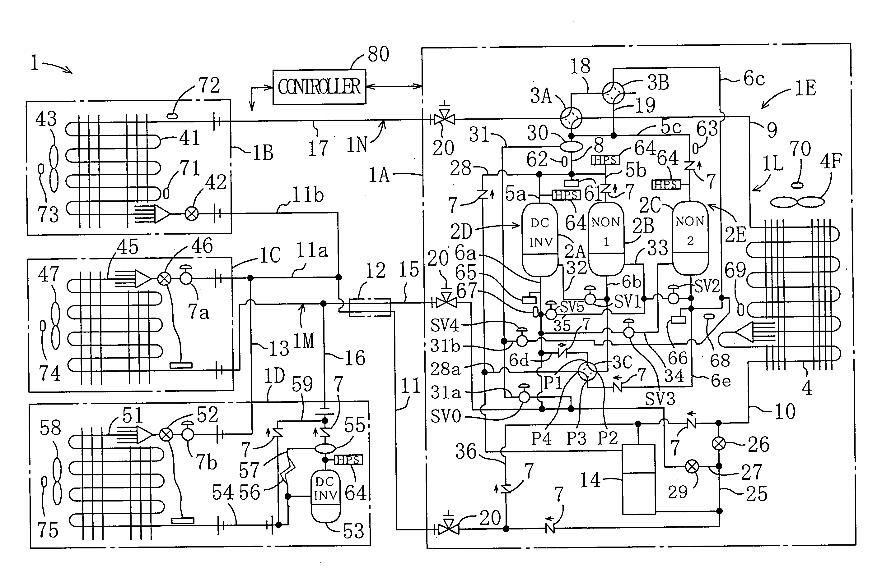
[0038] As shown in FIG. 1, a refrigerating apparatus (1) relating to this embodiment is installed at convenience stores and is used to perform cooling of cold-storage showcases and freezing showcases and air-cooling / heating in the stores.

[0039] The refrigerating apparatus (1) has an outdoor unit (1A), an indoor unit (1B), a cold-storage unit (1C) and a freezing unit (1D), and comprises a refrigerant circuit (1E) performing a vapor-compression refrigerating cycle. The refrigerant circuit (1E) is provided with a first channel side circuit for cold-storage / freezing and a second channel side circuit for air-conditioning. The refrigerant circuit (1E) is configured so as to be switched between an air-cooling cycle and an air-heating cycle.

[0040] The indoor unit (1B) is configured to perform an air-cooling operation and an air-heating operation by switching such operations and is ...


PUM


Abstract

In a refrigerating apparatus in which a plurality of application-side heat exchangers (41, 45, 51) are connected to a heat-source side heat exchanger (4), liquid lines for a plurality of channels in a refrigerant circuit (1E) share a liquid side communication pipe (11) in order to reduce the number of pipes. Further, the liquid side communication pipe (11) is provided adjacent to a low-pressure gas side communication pipe (15) for at least one channel so as to contact it in order to supercool a liquid refrigerant by a low-pressure gas refrigerant. Thus, workability for connecting the pipes is improved and a refrigerating ability may not be decreased even if communication pipes (11, 15, 17) become long.

Description

TECHNICAL FIELD [0001] The present invention relates to a refrigerating apparatus, and in particular to, a refrigerating apparatus which has application-side heat exchangers for a plurality of channels as cold-storage / freezing and air-conditioning heat exchangers. BACKGROUND ART [0002] Refrigerating apparatuses which perform a refrigerating cycle are conventionally known. The refrigerating apparatuses are widely utilized as an air-conditioning machine for performing air-cooling / heating in a room or a cooling machine such as a refrigerator for storing foods. Among the refrigerating apparatuses, there is a refrigerating apparatus which performs air-conditioning and cold-storage / freezing as disclosed in Japanese Patent Application Laid-Open (JP-A) No. 2001-280749. [0003] In this type of refrigerating apparatus, application-side heat exchangers provided in application-side units including cold-storage / freezing showcases and an air-conditioning indoor machine are connected in parallel to...

Claims


Application Information

Patent Timeline
Patent Type & Authority Applications(United States)
IPC IPC(8): F25B1/00F25B1/10F25B5/02F25B13/00F25B40/00
CPCF25B1/10F25B13/00F25B40/00F25B2313/007F25B2313/0231F25B2313/0233Y02B30/741F25B2400/075F25B2400/0751F25B2400/16F25B2400/22F25B2600/021F25B2313/02331Y02B30/70F25B29/00
Inventor TAKEGAMI, MASAAKITANIMOTO, KENJI
Owner DAIKIN IND LTD
Why Eureka
Try Eureka