Method for forming heated glass panels

a technology of heated glass and assembly method, which is applied in the direction of heater elements, resistive material coatings, electric vehicles, etc., can solve the problems of non-uniform coating, waste of energy, and insufficient use of coated glass, so as to achieve robust external electrical connection

Inactive Publication Date: 2005-06-02
ENGINEERED GLASS PRODS
View PDF48 Cites 41 Cited by
  • Summary
  • Abstract
  • Description
  • Claims
  • Application Information

AI Technical Summary

Benefits of technology

[0024] The present invention relates to depositing conductive metal on sheets of dielectric substrate materials, for example, bus bars on a surface of glass or on an electrically conductive coating that is disposed on a major surface of a glass sheet, the bus bars being deposited by way of a heating head and mask apparatus. In conjunction, the present invention relates to depositing and electrically contacting metallic tabs, which extend from the peripheral edge of the glass sheet to the metal bus bars, to the bus bars thus allowing robust external electrical connection to the electrically conductive coatings.

Problems solved by technology

At the present time, heating, cooking, moisture control, and the electrical control of such processes and activities do not take full advantage of the potential of the use of coated glass.
However, in the past, the film deposition techniques, such as those used in spray coating, were not precise, which resulted in non-uniform coatings and consequently imprecise heating.
However, non-uniform coatings and traditional electrical control methods result in wasted energy, produce hot and cold spots on the glass, and can result in safety hazards should the glass break and expose the current-carrying film.
For transportation applications, where heated windows and mirrors provide drivers and occupants of land, air, and water vehicles unimpeded viewing by the removal of condensation, breakage of the electrically heated glass panels can also result in electrical safety problems.
The use of glass enclosures does allow the contents to be seen, but the use of only base electrical ribbon element heaters does not allow for radiant heating techniques that would be advantageous for the warming of food items from an area above the food items.
Commercial buildings, sports stadium skyboxes, sloped glazing in atria, canopies, and general fenestration applications, could benefit from the use of electrically heated glass panels, but the underlying reason for the reluctance to adopt these technologies in architectural applications is the lack of an integrated connection circuit and a systems approach to these applications.
Expanding the adoption of these technologies, however, is hampered by the complexity of safely, reliably, and cost effectively combining glass and electricity.
Some of the problems that must be overcome by the electrical controls are: (a) electrical shock potential, (b) circuitry components releasing significant heat to the overall system, (c) overload of the integrated connection circuits that supply the power to the panels, (d) bulkiness of the parts used in the control method, (e) lack of mounting space for the parts, (f) electrical interference generated by the control method, (g) lack of predictability and complexity of the control method, and (h) overall serviceability and costs.
Disadvantages of this method are that capacitors of the required value are: (1) physically large and may be expensive, (2) when a capacitor fails, the full line voltage may be applied across the coated glass, (3) there is no integrated protection using such a method, so over-current protection must be provided, (4) handling many different applications is problematic, such that either a stock of a large number of different values of capacitors would be required or a large number of series-parallel networks must be constructed, which can also complicate the issues of required space and cost, and (5) the varying electrical phase angle may present power quality problems.
The use of electrical control circuits to operate the triacs, which in turn controls the current through the electrically conductive heated glass panel assembly and control systems, has the potential to minimize these negative effects, but to-date it has not been able to accomplish that task.
Consequently, the application of triacs has not fully been able to solve the aforementioned problems in the control of electrically conductive heated glass panel assembly systems.
These are difficult and expensive to print and difficult to solder external leads to, where special solder is required.
Further, various metallic tapes, including copper, have been attached to glass using adhesives but these connections exhibit poor adhesion to the glass.
Also, rigid electrical terminations at the edge of the glass result from these methods of applying the bus bars, which makes them vulnerable to mechanical flexing, can expose them to condensation, and typically are expensive.
Since power supply matching for each application is statically performed, the changing of system variables after manufacturing is, at best, cumbersome, while monitoring of system operating conditions is nearly nonexistent.

Method used


Image

  • Method for forming heated glass panels
  • Method for forming heated glass panels
  • Method for forming heated glass panels

Examples


Embodiment Construction

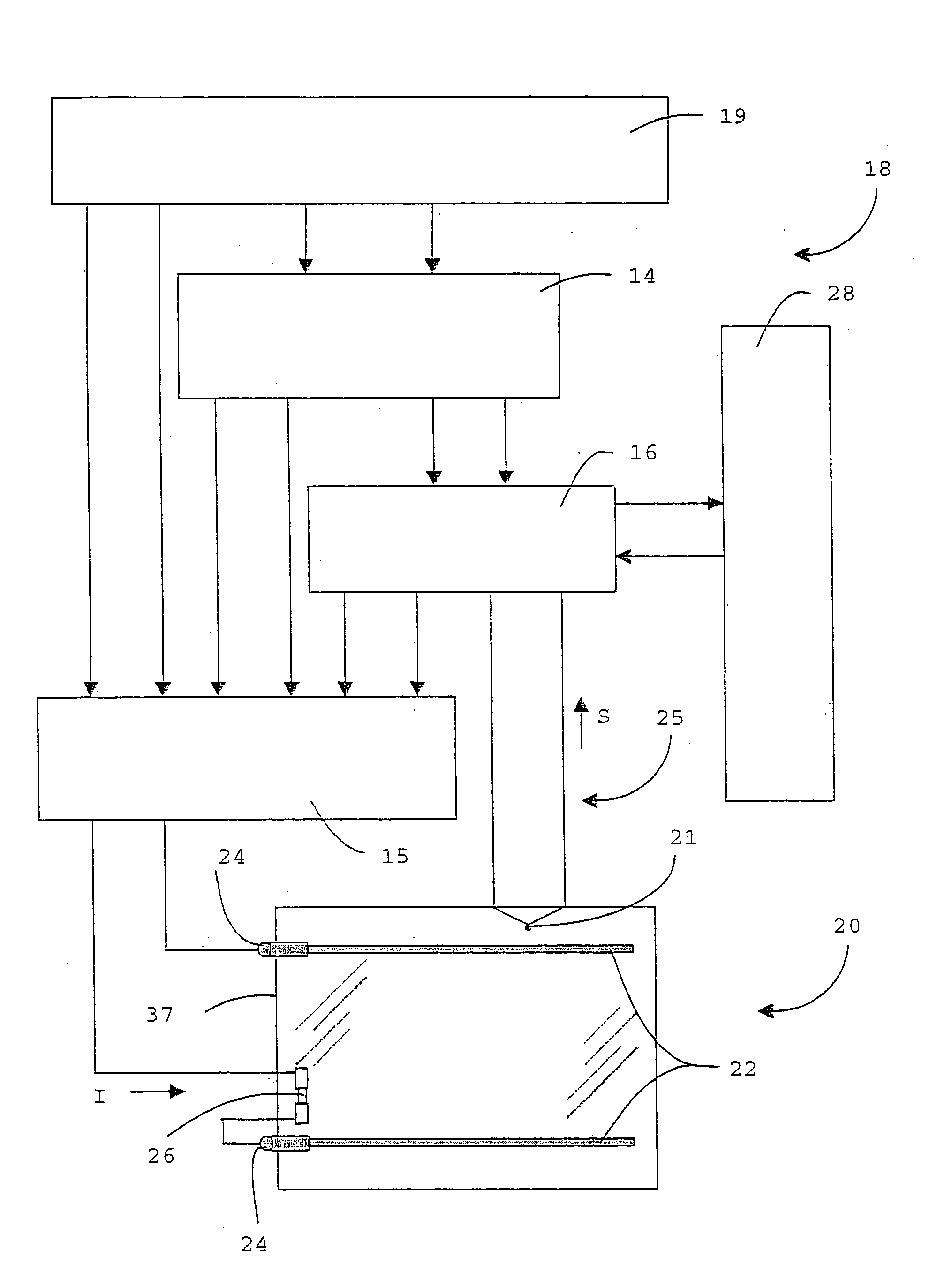
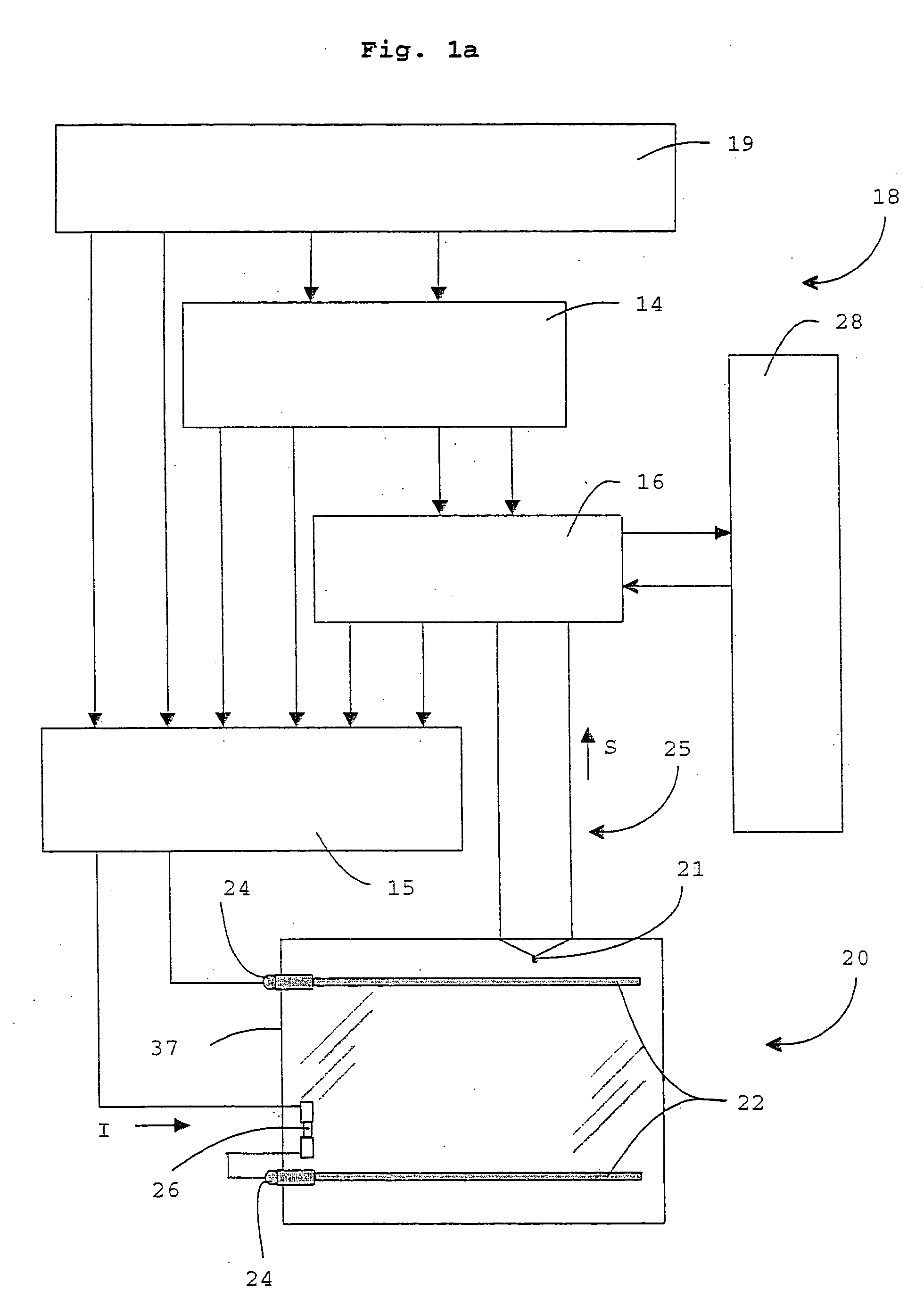
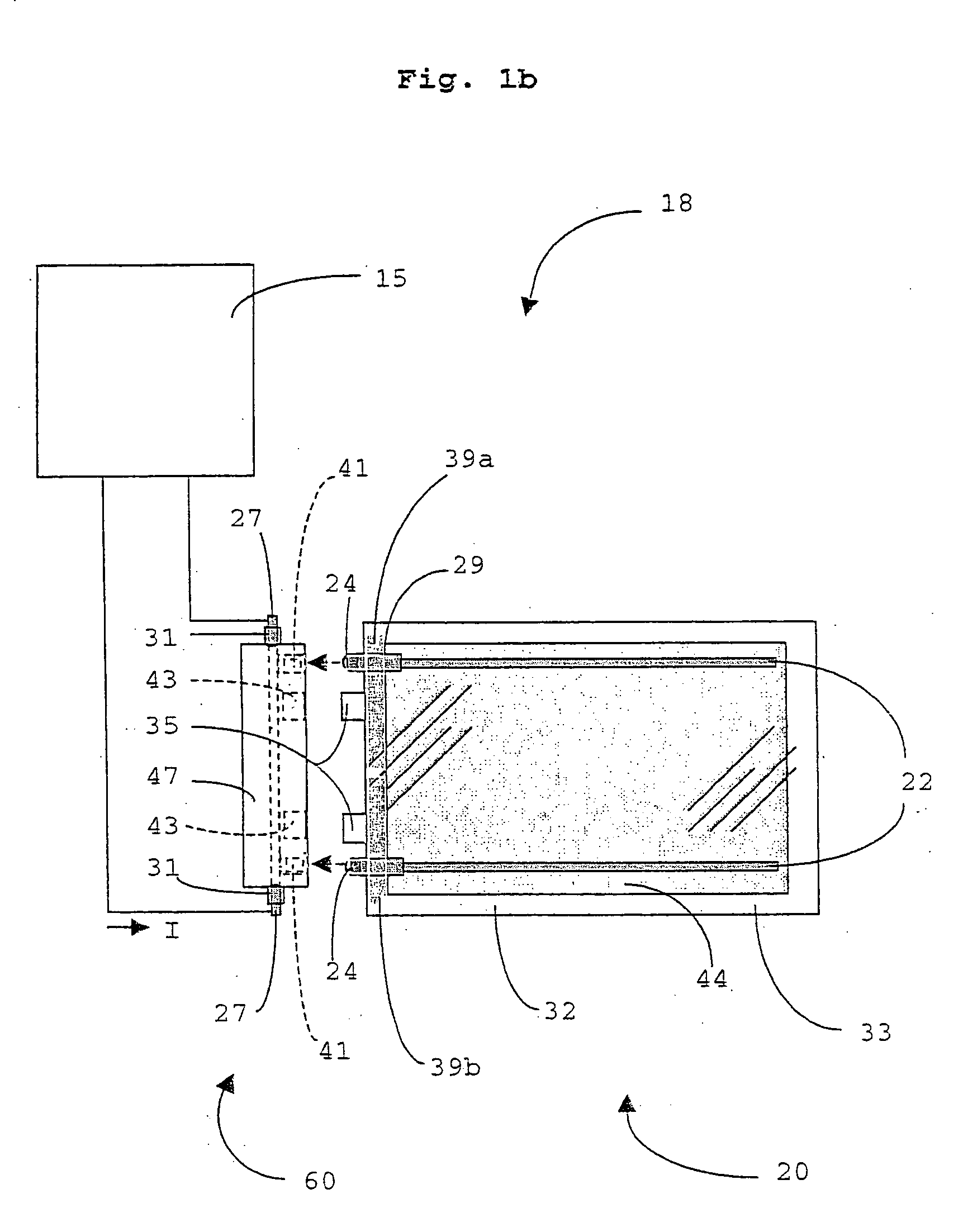
[0051] The present invention employs an integrated connection circuit 18, as shown in FIG. 1a, where electrical current (I) passes through a coating that is disposed on a sheet of a dielectric material, for example, an electrically conductive heated glass panel 20, to generate heat that can be used for warming, cooking, moisture control, and the like. The panel 20 may be realized within the present invention as a laminated panel 40, an insulated glass panel 30, or a combination thereof. The present invention has been found to apply to sheets that are dielectric substrate materials other than glass, for example, ceramic and glass-ceramic materials.

[0052] In order to control the electrical current (I) flowing through the electrically conductive heated glass panel 20, a solid-state controller 16, for example, a programmable application-specific integrated circuit (ASIC) chip, would monitor inputs like a signal (S) from a condition-sensing means, for example, a condition sensor 21. Exa...


PUM

PropertyMeasurementUnit
temperaturesaaaaaaaaaa
temperatureaaaaaaaaaa
electrically conductiveaaaaaaaaaa

Abstract

Methods for forming electrically conductive heated dielectric panels are provided. The panels are utilized for warming objects and / or insuring unobstructed viewing through the panels by removing moisture. The methods include depositing electrically conductive metal bus bars onto the dielectric panel, onto which panel a conductive coating has previously been disposed. The conductive metal bus bars are deposited onto the coated dielectric panel through the use of a circularly rotating or an inline heating head and mask apparatus, in combination with an oxyacetylene or a plasma device. A metallic tab, which extends from the panel peripheral edge, is brought into electrical contact with each conductive metal bus bar for external electrical connectivity.

Description

RELATED APPLICATIONS [0001] This application is a divisional application of and claims benefit, under 35 U.S.C. § 120, of pending U.S. patent application Ser. No. 10 / 833,572, filed Apr. 28, 2004, which is a divisional application of pending U.S. patent application Ser. No. 10 / 256,391, filed Sep. 27, 2002, which claims the benefit, under 35 U.S.C. § 119(e), of U.S. Provisional Patent Applications Ser. No. 60 / 339,409, filed Oct. 26, 2001, and Ser. No. 60 / 369,962, filed Apr. 4, 2002, under 35 U.S.C. § 111(b), which applications are incorporated herein in their entireties. [0002] This application also claims benefit, under 35 U.S.C. § 120, of pending U.S. patent application Ser. No. 10 / 403,924, filed Mar. 26, 2003, which application also claims the benefit, under 35 U.S.C. § 119(e), of U.S. Provisional Patent Applications Ser. No. 60 / 369,962, filed Apr. 4, 2002 under 35 U.S.C. § 111(b).BACKGROUND OF THE INVENTION [0003] The present invention generally relates to electrically conductive ...

Claims


Application Information

Patent Timeline
Patent Type & Authority Applications(United States)
IPC IPC(8): A47F3/04B32B17/10C03C17/23C23C28/00F24C15/04H05B3/00H05B3/02H05B3/03H05B3/10H05B3/84
CPCA47F3/0434B32B17/10036B32B17/10376B32B17/10761B60L1/02B60L8/003Y10T29/49099H05B2203/016Y02T10/7083B60L2200/26Y10T29/49083Y10T29/435H05B3/84Y02T10/7072
Inventor GERHARDINGER, PETER F.BAUMAN, RANDALL L.ASHTON, DILLON R.
Owner ENGINEERED GLASS PRODS
Why Eureka
Try Eureka