Non-lethal nose cone design

Inactive Publication Date: 2005-06-02
UNITED DEFENSE LP
View PDF5 Cites 8 Cited by
  • Summary
  • Abstract
  • Description
  • Claims
  • Application Information

AI Technical Summary

Benefits of technology

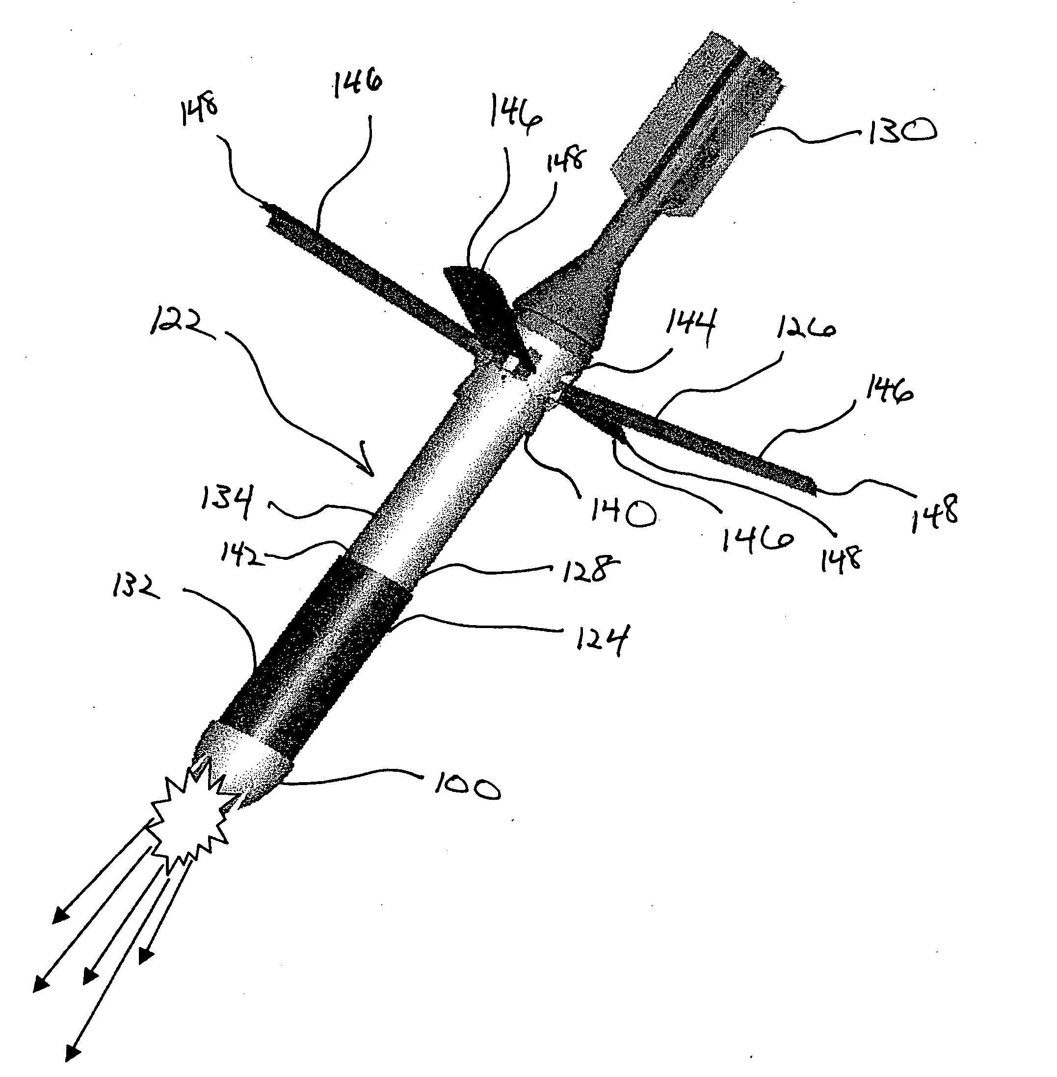
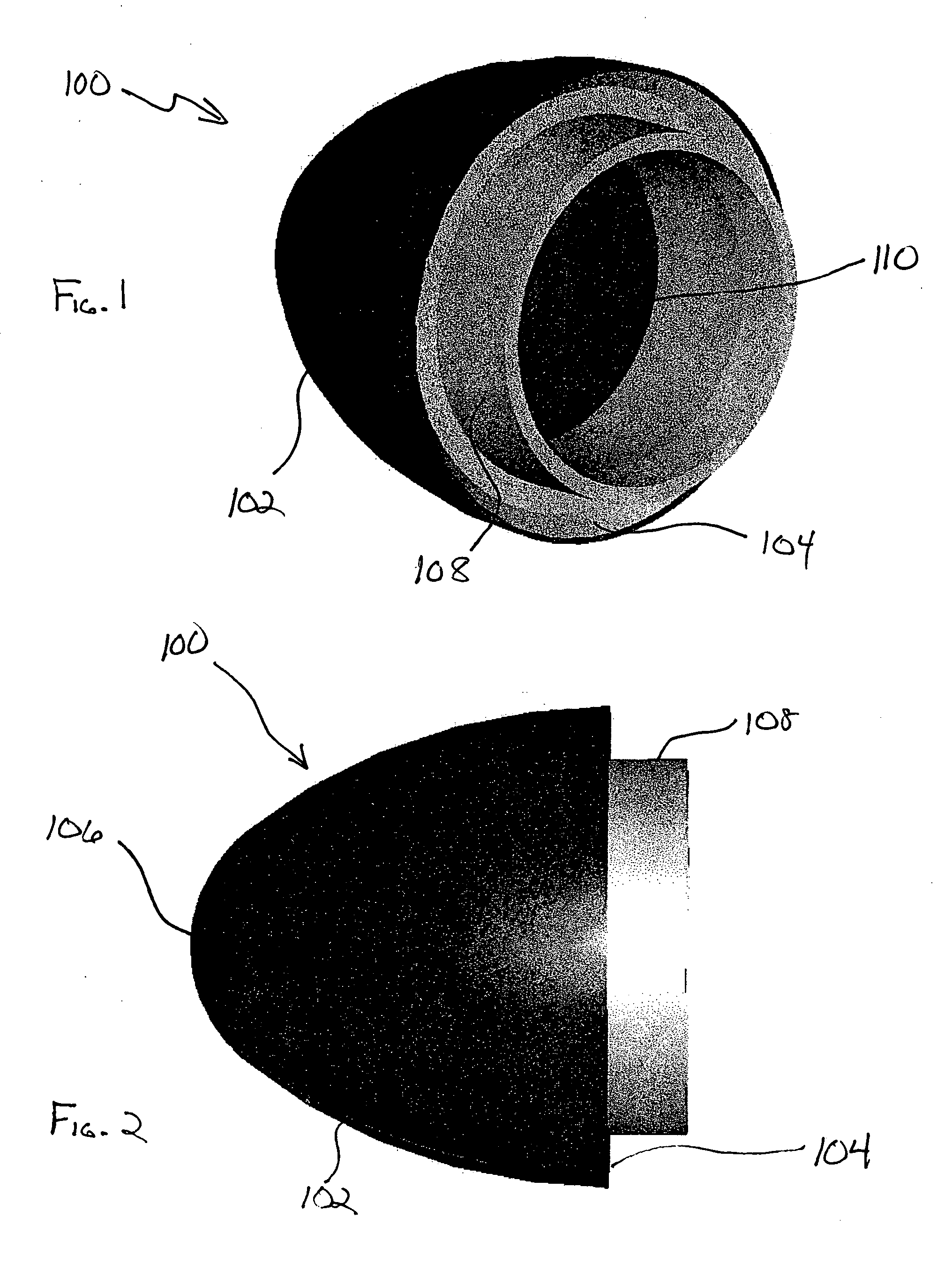
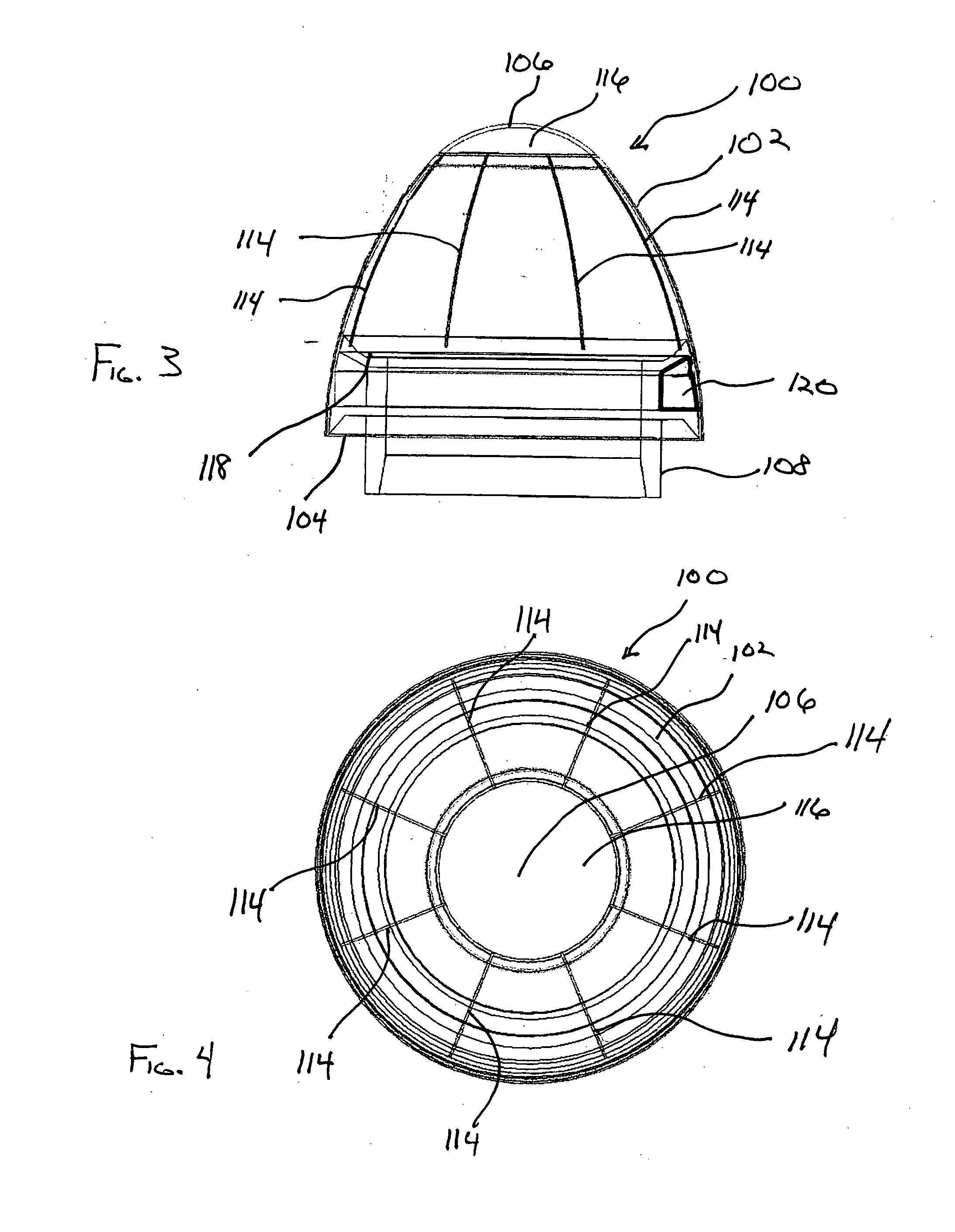
[0009] The present invention comprises a non-lethal nose cone adapted for the delivery of non-lethal munitions with a projectile weapon. Generally, the non-lethal nose cone of the present invention is manufactured of materials, such as polymers and ceramics, selected for traits including high strength and uniformity when exposed to typical projectile firing conditions. The material selection avoids the conventional hazards of nose cone design wherein detonation of an internal charge disperses shrapnel. The non-lethal nose cone may also include a planned failure mode so that the nose cone opens in a petal like configuration upon impact of the internal munition.
[0010] Generally, the non-lethal nose cone of the present invention is intended for use with a projectile incorporating a projectile kinetic energy reduction system such as described in U.S. patent application Ser. No. 10 / 355,541 entitled “Projectile Kinetic Energy Reduction System”. The projectile kinetic energy reduction system dramatically reduces the forward momentum of the projectile and then directs the descent at a non-lethal rate. The projectile kinetic energy system serves the dual-functions of assisting with ejection of a submunition through the non-lethal nose cone as well as reducing the fall rate of the projectile structure to non-lethal velocities of approximately less than 11 m / s (24.6 mph).

Problems solved by technology

Even when the use of lethal force may be required, the military, political and social repercussions from such force may dissuade a commander from its application.
Thus a wide number of traditional military weapons provided to deployed personnel cannot be used for crowd control missions.
While these projectiles can be used effectively, they all suffer the downside of requiring the military personnel to be in close proximity to the targets.
As such, the military personnel are exposed to the risk of return fire.
However, even the standoff systems have a downside in that the delivery vehicle itself may create a hazard as it falls to the earth.

Method used


Image

  • Non-lethal nose cone design
  • Non-lethal nose cone design
  • Non-lethal nose cone design

Examples


Embodiment Construction

[0022] The present invention comprises a non-lethal nose cone adapted for the delivery of non-lethal munitions with a projectile weapon. Typical projectile nose cones are constructed to separate into many individual pieces upon a triggering event, with each individual piece having sufficient kinetic energy to cause bodily harm. The present invention provides a design to eliminate the lethal aspect of payload dispersal. Generally, the non-lethal nose cone of the present invention is manufactured of materials, such as polymers and ceramics, selected for traits including high strength and uniformity when exposed to typical projectile firing conditions as well as their ability to avoid becoming lethal shrapnel upon detonation of an internal charge for disbursing the non-lethal munitions through the nose cone.

[0023] As depicted in FIGS. 1 and 2, a non-lethal nose cone 100 of the present invention comprises a nose cone body 102 having a generally, circular cross-section radiused from an ...


PUM


Abstract

A non-lethal nose cone adapted for the delivery of non-lethal munitions with a projectile weapon. The non-lethal nose cone is manufactured of materials, such as polymers and ceramics, selected for traits including high strength and uniformity when exposed to typical projectile firing conditions as well as an ability to avoid becoming lethal shrapnel upon detonation of an internal charge for disbursing the non-lethal submunitions through pre-scored grooves on the nose cone. Generally, the non-lethal nose cone is intended for use with a projectile having an integral kinetic energy reduction system that may serve the dual role of assisting with submunition ejection through the pre-scored grooves as well as reducing the fall rate of the projectile to non-lethal velocities. Generally, the non-lethal nose cone is adapted for use with standoff delivery systems such as mortar rounds, air delivery systems and artillery.

Description

RELATED APPLICATIONS [0001] This application is a continuation-in-part of U.S. patent application Ser. No. 10 / 355,541 entitled “Projectile Kinetic Energy Reduction System” filed May 6, 2003.FIELD OF THE INVENTION [0002] The present invention relates generally to the field of military projectiles. More specifically, the present invention relates to a non-lethal projectile nose cone design adapted for standoff delivery of non-lethal munitions. BACKGROUND OF THE INVENTION [0003] In recent years, the role of the military has evolved beyond its traditional battlefield mission. Troops are as likely to be deployed in response to political peacekeeping missions as they are for traditional combat. To accommodate these new missions, military weapons and tactics must evolve and be adapted for use in these new roles. [0004] An example of where new weapons and tactics are necessary is in crowd control of hostile groups of non-combatants in areas under occupation by the military. For both politic...

Claims


Application Information

Patent Timeline
IPC IPC(8): F42B12/74F42B25/00F42B30/10
CPCF42B12/74F42B30/10F42B25/00
Inventor WELTY, THOMAS C.BERG, RANDY E.FREDRICKSON, THOMAS D.JOHNSON, RICHARD F.
Owner UNITED DEFENSE LP
Why Eureka
Try Eureka