Electroluminescent display device and thermal transfer donor film for the electroluminescent display device

a technology of electroluminescent display device and donor film, which is applied in the direction of discharge tube luminescnet screen, discharge tube/lamp details, electric discharge lamps, etc., can solve the problems of external light emission, reflection reduction, and reduced external efficiency, and achieve the effect of increasing the light extraction efficiency of the light-emitting portion

Active Publication Date: 2005-06-02
SAMSUNG DISPLAY CO LTD
View PDF6 Cites 53 Cited by
  • Summary
  • Abstract
  • Description
  • Claims
  • Application Information

AI Technical Summary

Benefits of technology

[0020] According to another aspect of the present invention, there is provided an organic EL display device which includes a substrate. A stack formed on the substrate includes: a first electrode layer formed with a predetermined pattern on the substrate; a second electrode layer and an organic light-emitting portion formed on the first electrode layer; a photonic crystal layer that increases a light extraction efficiency of the light-emitting portion; a refractive layer interposed between the photonic crystal layer and the stack such that the refractive layer is formed directly on the stack. In one embodiment, the refractive layer may be a material having a different refractive index than the material of which the photonic crystal layer is composed.

Problems solved by technology

A problem is that external efficiency is reduced when light emitted from the organic light-emitting layer has an outgoing angle greater than a critical angle of one of the layers.
Reflection reduces the light, and causes it to emit externally.
This requirement complicates the manufacturing process, making it difficult to attain efficient productivity.
Also, the formation of an organic layer on the irregularities in the surface of the substrate or the fine electrode pattern layer increases the overall roughness of the organic layer, which increases current leakage.
Current leakage, in turn, deteriorates the durability and reliability of the organic EL device.
Otherwise screen display quality degrades.
However, such constraints limit the design and manufacture of EL display devices.
Such problems also apply to active matrix (AM) organic EL display devices.

Method used


Image

  • Electroluminescent display device and thermal transfer donor film for the electroluminescent display device
  • Electroluminescent display device and thermal transfer donor film for the electroluminescent display device
  • Electroluminescent display device and thermal transfer donor film for the electroluminescent display device

Examples


Embodiment Construction

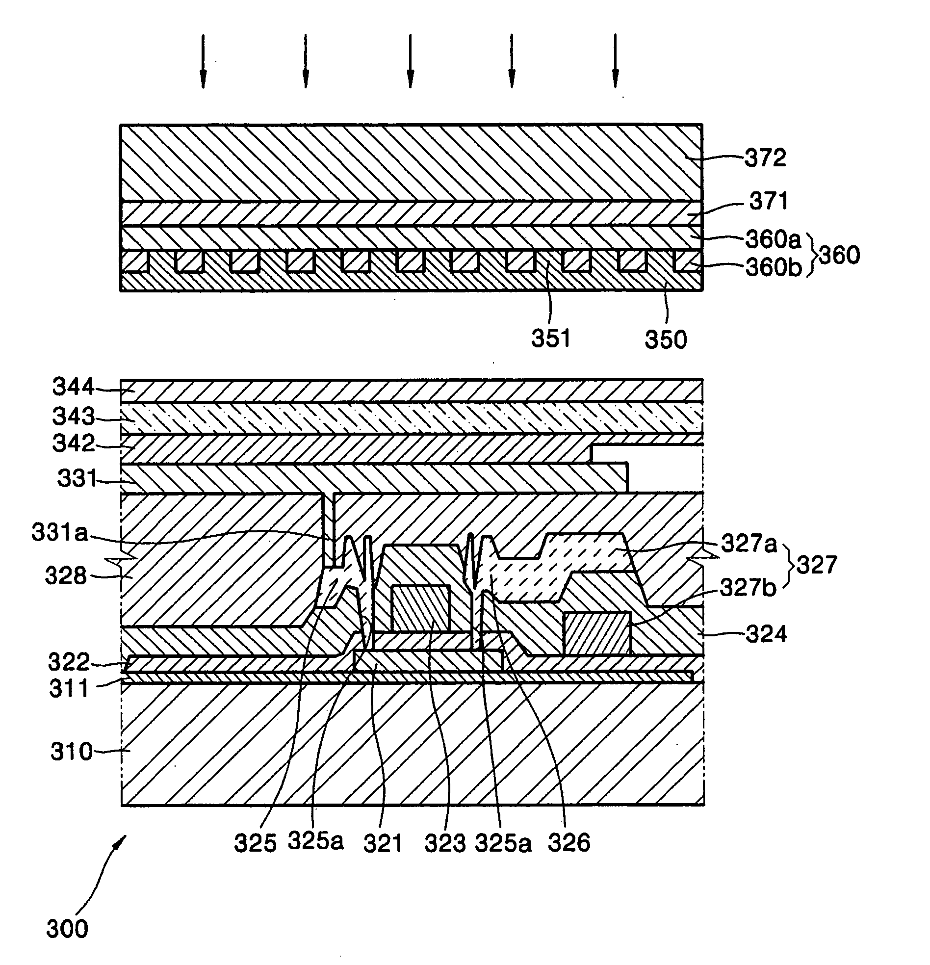
[0027] The claimed invention relates to an improved electroluminescent (EL) display device having an improved efficiency of light transmission by use of a refractive material and a photonic crystal layer. The invention is further directed to a thermal transfer layer which is used to build the photonic crystal layer and to transfer it to an upper surface of the stack.

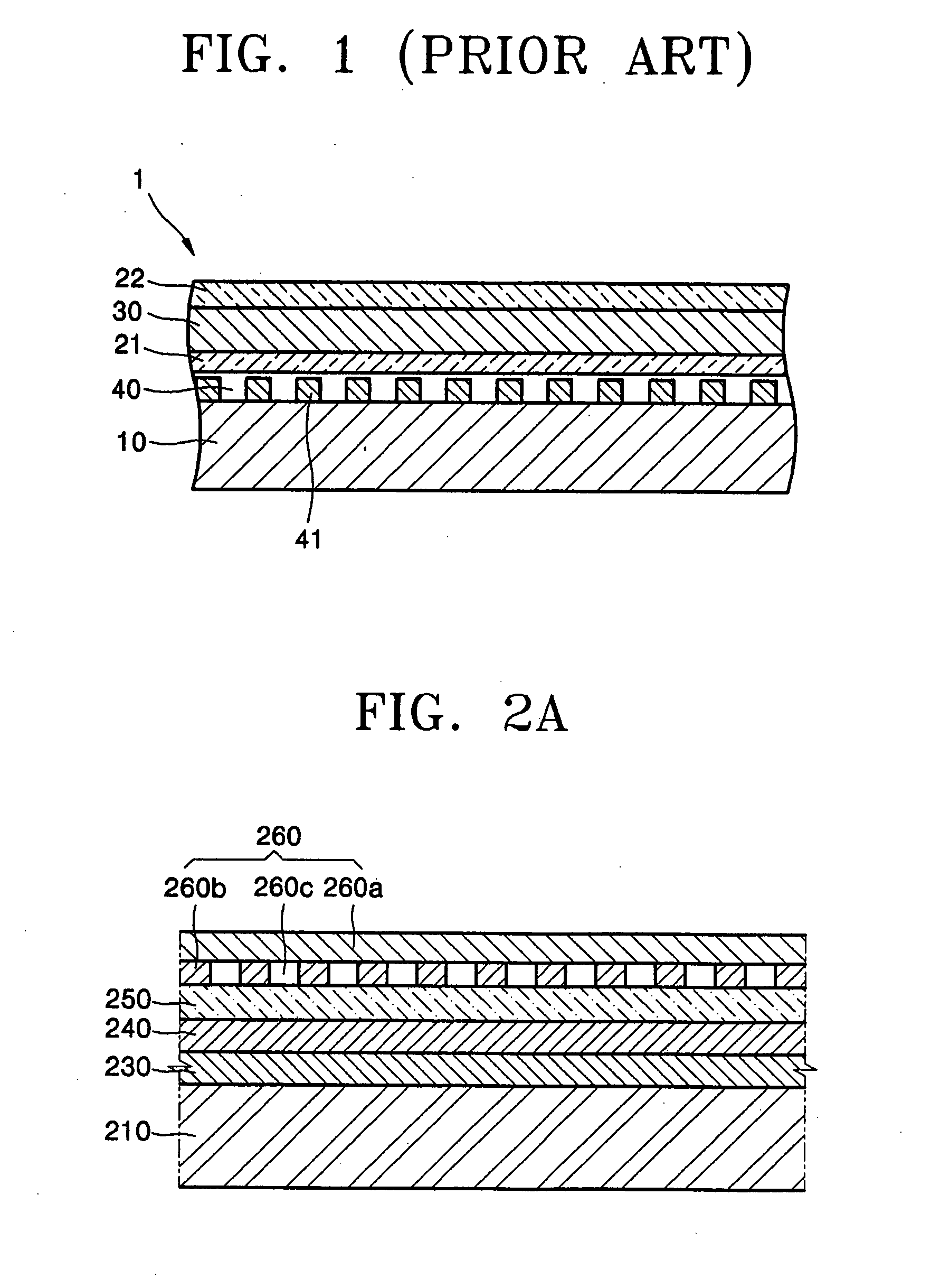
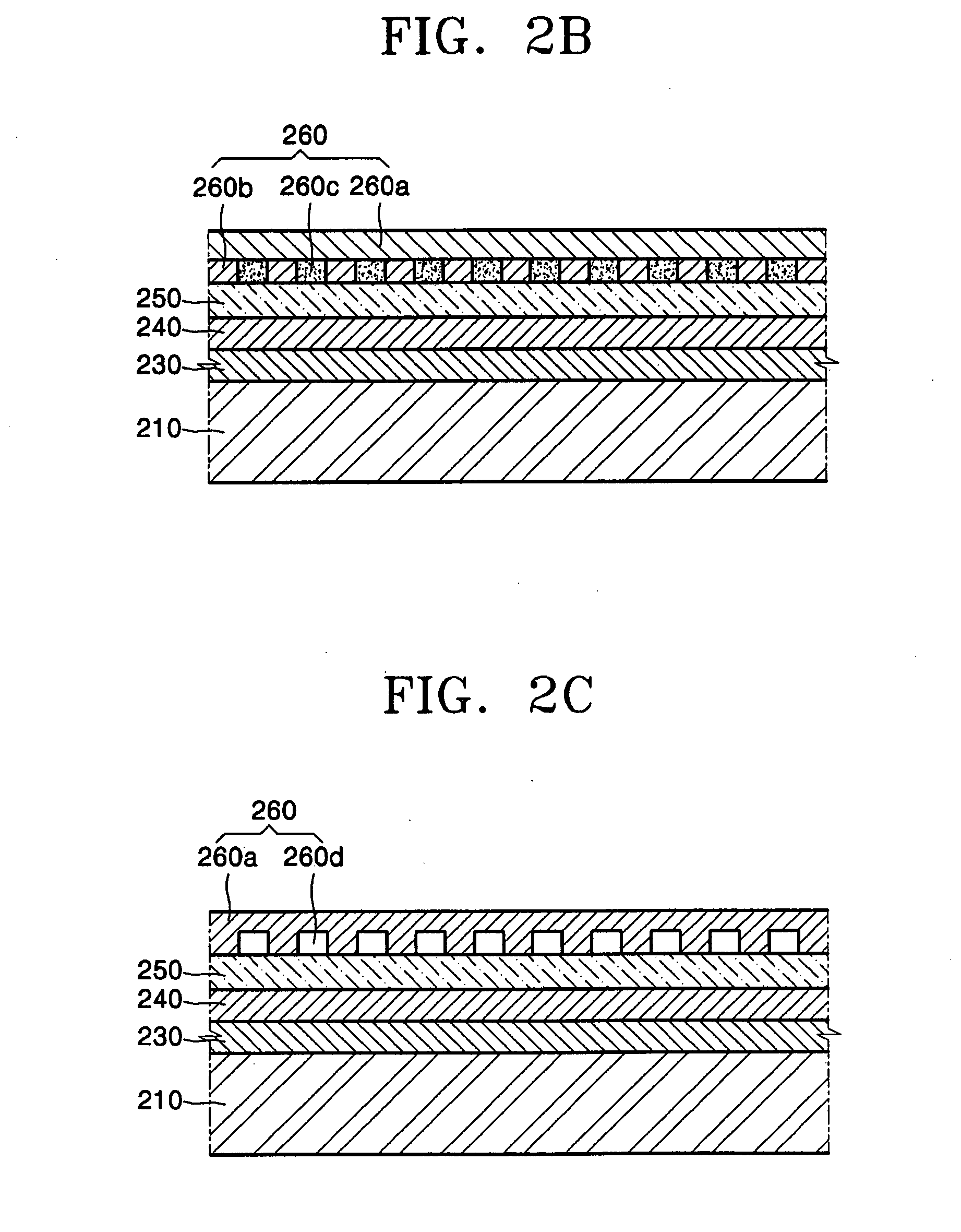
[0028]FIGS. 2A through 2D are cross sectional views of an organic electroluminescent (EL) display device according to embodiments of the present invention. The organic EL display device according to an embodiment of the present invention includes a substrate 210, on which a first electrode layer 230 is formed in a pattern. An organic light-emitting portion 240 is formed on the first electrode layer. A second electrode layer 250 is formed on the organic light emitting portion 240. A photonic crystal layer 260 which increases the light extraction efficiency of the an organic light-emitting is formed on the second electrod...


PUM


Abstract

The invention is directed to an organic electroluminescent (EL) display device having an improved light extracting efficiency due to a photonic crystal layer formed proximate one side of a stack. Among other elements, the stack may include a first electrode formed on a substrate, an organic light emitting layer formed above the first electrode, and a second electrode formed above the organic light emitting layer. Additionally, the photonic crystal layer may be configured to correspond to a wavelength of colored light. An organic EL display device having an improved light extracting efficiency may be manufactured using a thermal transfer donor film to adhere the photonic crystal layer to the stack.

Description

[0001] This application claims the benefit of Korean Patent Application No. 2003-85819, filed on Nov. 28, 2003, in the Korean Intellectual Property Office, which is herein incorporated by reference. BACKGROUND OF THE INVENTION [0002] 1. Field of the Invention [0003] The present invention relates to an organic electroluminescent (EL) display device and a thermal transfer donor film used in manufacturing an organic EL display device. More particularly, the invention relates to an EL display device having a high efficiency of light extraction from an organic light-emitting portion. The higher efficiency is caused in part by a photonic crystal layer located directly on a stack formed on the substrate. Additionally, a laser induced thermal transfer donor film for the EL display device is used to form the photonic crystal layer on the stack. [0004] 2. Description of the Related Art [0005] An electroluminescent (EL) display device forms viewable images by reflecting or shining light throug...

Claims


Application Information

Patent Timeline
Patent Type & Authority Applications(United States)
IPC IPC(8): H01L27/32H01L51/50H05B33/02H01L51/52H01L51/56H05B33/00H05B33/10H05B33/12H05B33/14H05B33/22
CPCH01L27/3211H01L27/322H01L51/56H01L51/5275H01L27/3244H10K59/35H10K59/38H10K59/12H10K50/858H10K71/00H05B33/22
Inventor PARK, JIN-WOOCHUNG, HO-KYOONKWON, JANG-HYUKKIM, MU-HYUNSONG, SEUNG-YONGDO, YOUNG-RAGKIM, YOON-CHANGKANG, TAE-MINLEE, SEONG-TAEK
Owner SAMSUNG DISPLAY CO LTD
Why Eureka
Try Eureka