Back-light driving circuit in field sequential liquid crystal display

a back-light driving circuit and liquid crystal display technology, applied in the direction of instruments, lighting and heating apparatus, process and machine control, etc., can solve the problems of forward driving voltage, power consumption increase, and need for fast operating characteristics, so as to maximize the efficiency of the driving circuit and reduce power consumption

Inactive Publication Date: 2005-06-02
SAMSUNG MOBILE DISPLAY CO LTD
View PDF7 Cites 37 Cited by
  • Summary
  • Abstract
  • Description
  • Claims
  • Application Information

AI Technical Summary

Benefits of technology

[0025] The various embodiments of the present invention provide a back-light driving circuit providing driving voltages suitable for each light emitting diode regardless of the distribution of driving currents of the light emitting diodes. The catering of the driving voltages to the particular characteristic of the corresponding light emitting diode helps decrease power consumption and helps maximize efficiency of the driving circuit.

Problems solved by technology

However, because the field sequential driving mode divides one frame into three sub-frames, it requires fast operating characteristics.
Since the R, G, and B light emitting diodes are provided with the same driving voltage during the three sub-frames of a single frame used to drive the R, G and B light emitting diodes, power consumption is increased.
Another problem is that the forward driving voltages provided to the R, G and B light emitting diodes in each sub-frame need to be manually adjusted using the variable resistors.
When distribution of driving currents of the light emitting diodes is large, it is difficult to provide the forward driving voltages suitable for the respective R, G and B light emitting diodes by only manually adjusting them using the variable resistors.

Method used


Image

  • Back-light driving circuit in field sequential liquid crystal display
  • Back-light driving circuit in field sequential liquid crystal display
  • Back-light driving circuit in field sequential liquid crystal display

Examples


Embodiment Construction

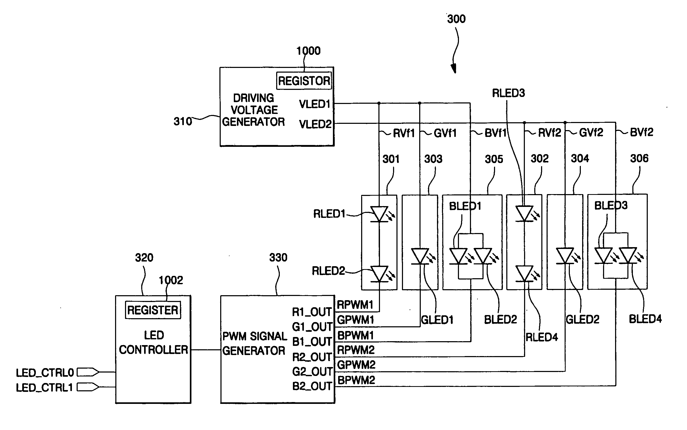
[0044]FIG. 3 is a schematic diagram illustrating a configuration of a back-light driving circuit used in a field sequential liquid crystal display in accordance with an embodiment of the present invention.

[0045] The back-light driving circuit according to the embodiment in FIG. 3 sequentially provides forward driving voltages suitable for respective R, G and B light emitting diodes (RLED, GLED and BLED) to R, G and B back-lights 301, 303 and 305, and drives the respective R, G and B light emitting diodes (RLED, GLED and BLED) by the forward driving voltages so as to achieve a luminance adjusted color. The back-light driving circuit also optimizes chromaticity by controlling different PWM values (RPWM, GPWM and BPWM) suitable for the R, G and B light emitting diodes (RLED, GLED and BLED). According to one embodiment, Pulse Width Modulation (PWM) values for the respective R, G and B light emitting diodes (RLED, GLED and BLED) are different from one another.

[0046] For example, in the...


PUM

PropertyMeasurementUnit
time intervalaaaaaaaaaa
timeaaaaaaaaaa
driving voltageaaaaaaaaaa

Abstract

A back-light driving circuit controlling red (R), green (G), and blue (B) back lights providing light to a liquid crystal panel in a field sequential liquid crystal display. The back-light driving circuit includes a driving voltage generator that provides a driving voltage to each of the R, G, and B back-lights to cause them to emit light having a predetermined luminance. The back-light driving circuit also includes a pulse width modulation (PWM) signal generator for providing a PWM signal to each of the R, G, and B back-lights to control the chromaticity of the light emitted from each back-light. The driving voltages and / or PWM signals provided to each of the R, G, and B back-lights are catered to the particular characteristics of the corresponding back-light to cause them to emit color having a desired luminance and / or chromaticity.

Description

CROSS-REFERENCE TO RELATED APPLICATION [0001] This application claims priority to and the benefit of Korean Patent Application No. 2003-0084780, filed Nov. 27, 2003, the disclosure of which is incorporated herein by reference in its entirety. BACKGROUND OF THE INVENTION [0002] 1. Field of the Invention [0003] The present invention relates to a field sequential liquid crystal display (FS-LCD), and more particularly, to an LCD capable of obtaining desired chromaticity and luminance regardless of a driving current distribution of a light emitting diode (LED). [0004] 2. Description of Related Art [0005] A color LCD generally includes a liquid crystal panel having an upper substrate, a lower substrate, and a liquid crystal injected between the upper and lower substrates. The color LCD further includes a driving circuit for driving the liquid crystal panel, and a back-light for providing white light to the liquid crystal. Such an LCD may be mainly classified into a red (R), green (G), blu...

Claims


Application Information

Patent Timeline
Patent Type & Authority Applications(United States)
IPC IPC(8): G09G3/20G02F1/133G09G3/34G09G3/36G09G5/02G09G5/10H05B37/02H05B44/00
CPCG09G3/3413G09G2320/0242G09G2320/0633G09G2320/064Y02B20/346H05B33/0818H05B33/0827H05B33/0857G09G2330/021H05B45/46G02F1/133Y02B20/30
Inventor KIM, TAE-SOO
Owner SAMSUNG MOBILE DISPLAY CO LTD
Why Eureka
Try Eureka