Measuring method and apparatus using shearing interferometry, exposure method and apparatus using the same, and device manufacturing method

a technology of shearing interferometry and measurement method, applied in the direction of photomechanical apparatus, instruments, optics, etc., can solve the problems of inevitable optical contrast deterioration in the signal component, the interferometer has a problem, and the two physically different grating surfaces are extremely difficult to control in such a range, so as to achieve the effect of easy signal processing and high precision

Inactive Publication Date: 2005-06-02
CANON KK
View PDF19 Cites 20 Cited by
  • Summary
  • Abstract
  • Description
  • Claims
  • Application Information

AI Technical Summary

Benefits of technology

[0010] Accordingly, it is an illustrative object of the present invention to provide a measuring method and apparatus which utilize the shearing interferometry and provide higher precision and easier signal processing than the conventional method, an exposure method and apparatus using them, and a device manufacturing method.

Problems solved by technology

However, this interferometer has a problem shown in FIG. 5.
Therefore, the above problem occurs when a position in the optical-axis direction (or z direction) offsets from F to G in FIG. 5 due to stage's driving errors, influence of the vibration, etc., during a replacement of the diffraction grating from B to C.
One design example needs to maintain ΔF to be about 10 nm in order to reduce the astigmatism error down to 0.1 nm RMS or smaller, and it is extremely difficult to control two physically different grating surfaces in such a range.
Patrik can avoid this problem, but causes new problems of inevitable optical contrast deteriorations in the signal component and extremely complex signal processing.

Method used


Image

  • Measuring method and apparatus using shearing interferometry, exposure method and apparatus using the same, and device manufacturing method
  • Measuring method and apparatus using shearing interferometry, exposure method and apparatus using the same, and device manufacturing method
  • Measuring method and apparatus using shearing interferometry, exposure method and apparatus using the same, and device manufacturing method

Examples


Embodiment Construction

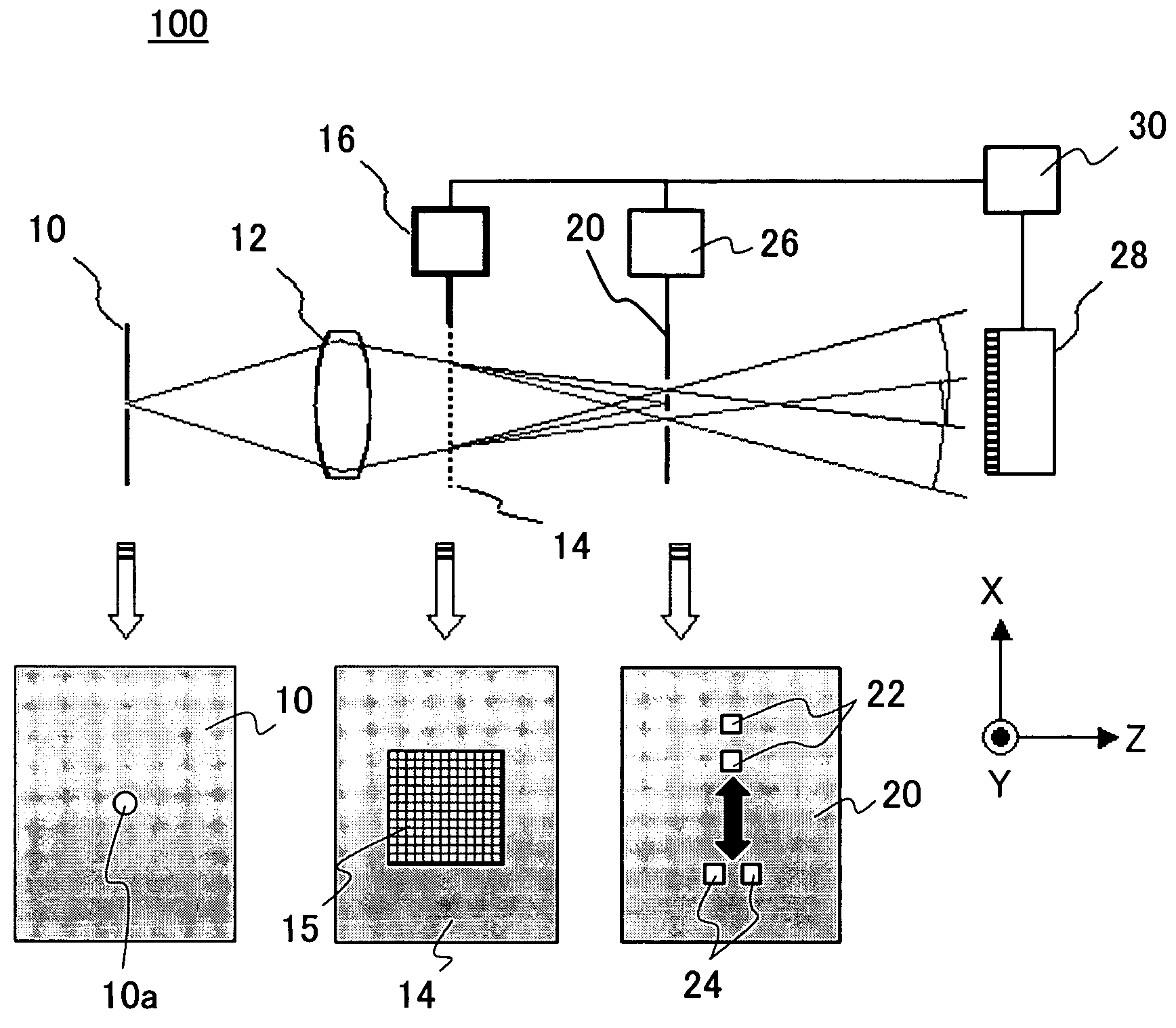
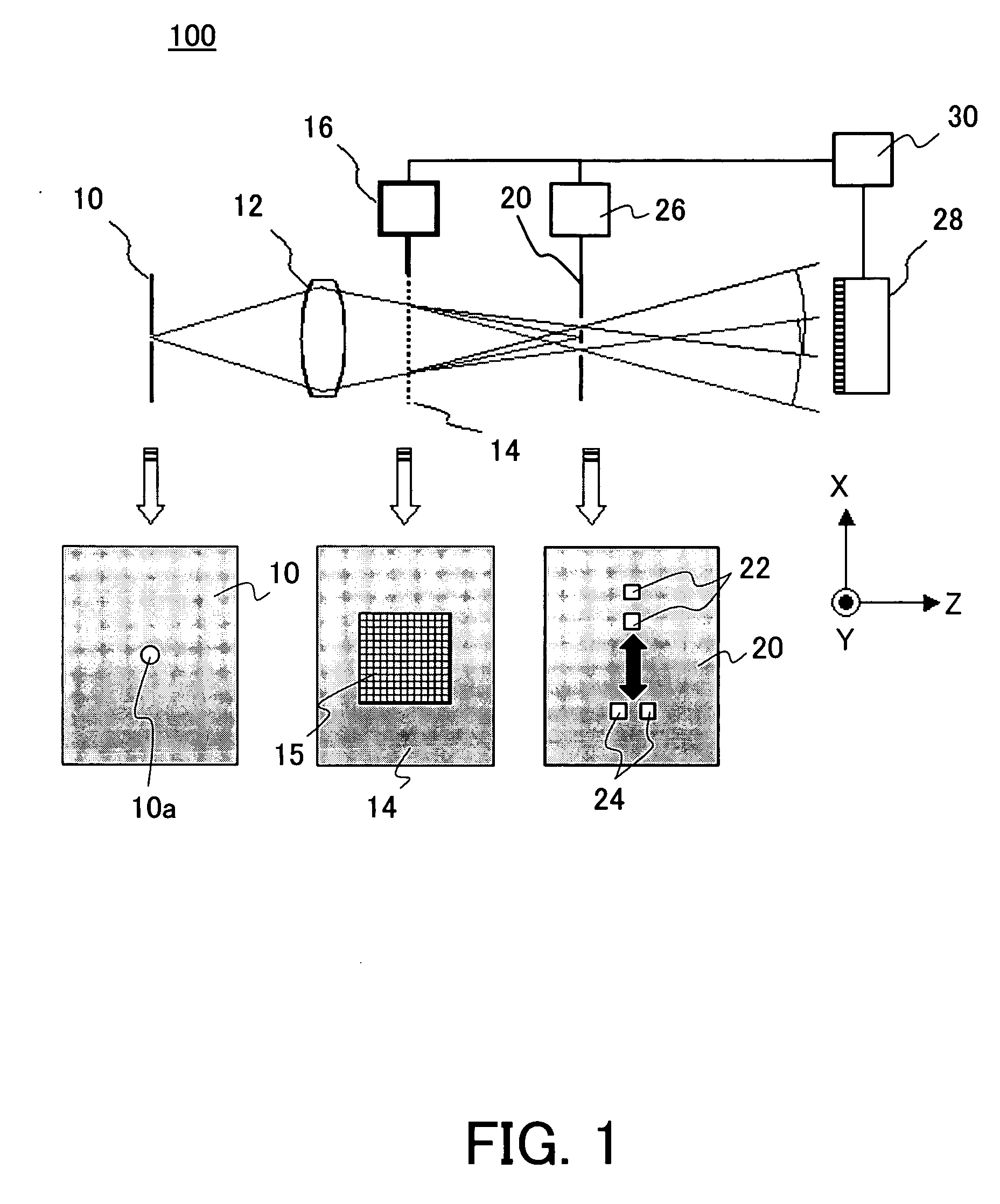
[0026]FIG. 1 shows a basic arrangement of the measuring apparatus 100 according to one embodiment of the present invention. The measuring apparatus 100 includes a pinhole plate 10, a target optical system 12, a diffraction grating 14, a stage 16 for the diffraction grating 14, a selecting window plate 20, a stage 26 for the selecting window plate 20, a detector 28, and a controller 30. While FIG. 1 shows the target optical system 12 as a lens, it is a reflection optical system when the exposure apparatus uses the EUV light as a light source.

[0027] The pinhole plate 10 has a pinhole 10a that generates a spherical wave that serves as the measurement light, and is arranged at a desired measurement point on the object surface of the target optical system 12. In an EUV exposure optical system having an NA of 0.25, the NA at the illumination optical system side is about 0.0625, and a diameter of the pinhole 10a is 13.5 / (2×0.0625)=108 nm to cover this range of the diffraction angle. There...


PUM

PropertyMeasurementUnit
wavelengthaaaaaaaaaa
diameteraaaaaaaaaa
thicknessaaaaaaaaaa

Abstract

A measuring apparatus includes a first mask having a pinhole for generating a spherical wave as measuring light, a second mask provided subsequent to the first mask in a light traveling direction, the second mask having a selecting window that allows the measuring light that has passed a target optical system to transmit through the selecting window, and a two-dimensional light divider, located between the first and second masks, for two-dimensionally dividing light, wherein the measuring apparatus calculating optical performance of the target optical system from an interference fringe formed by the measuring light that has passed the selecting window.

Description

BACKGROUND OF THE INVENTION [0001] The present invention relates generally to measuring method and apparatus, and more particularly to a measuring method and apparatus that use the shearing interferometry to measure a wave front aberration of a target optical system, such as a projection optical system that transfers a mask pattern onto an object, and an exposure method and apparatus using the measuring method and apparatus. The inventive measuring method and apparatus is suitable, for example, for a measurement of a projection optical system in an exposure apparatus that utilizes the extreme ultraviolet (“EUV”) light. [0002] A projection exposure apparatus is used to transfer a pattern on a mask (or a reticle) onto an object to be exposed in manufacturing semiconductor devices, etc. in the photolithography process. This exposure apparatus is required to transfer the pattern on the reticle onto the object precisely at a predetermined magnification. For this purpose, it is important ...

Claims


Application Information

Patent Timeline
Patent Type & Authority Applications(United States)
IPC IPC(8): G01B9/02G03F7/20G01M11/02H01L21/027
CPCG03F7/706
Inventor HASEGAWA, MASANOBU
Owner CANON KK
Why Eureka
Try Eureka