
Image processing method and appparatus for red eye correction

Inactive Publication Date: 2005-06-02
NK WORKS CO LTD
View PDF7 Cites 22 Cited by
  • Summary
  • Abstract
  • Description
  • Claims
  • Application Information

AI Technical Summary

Benefits of technology

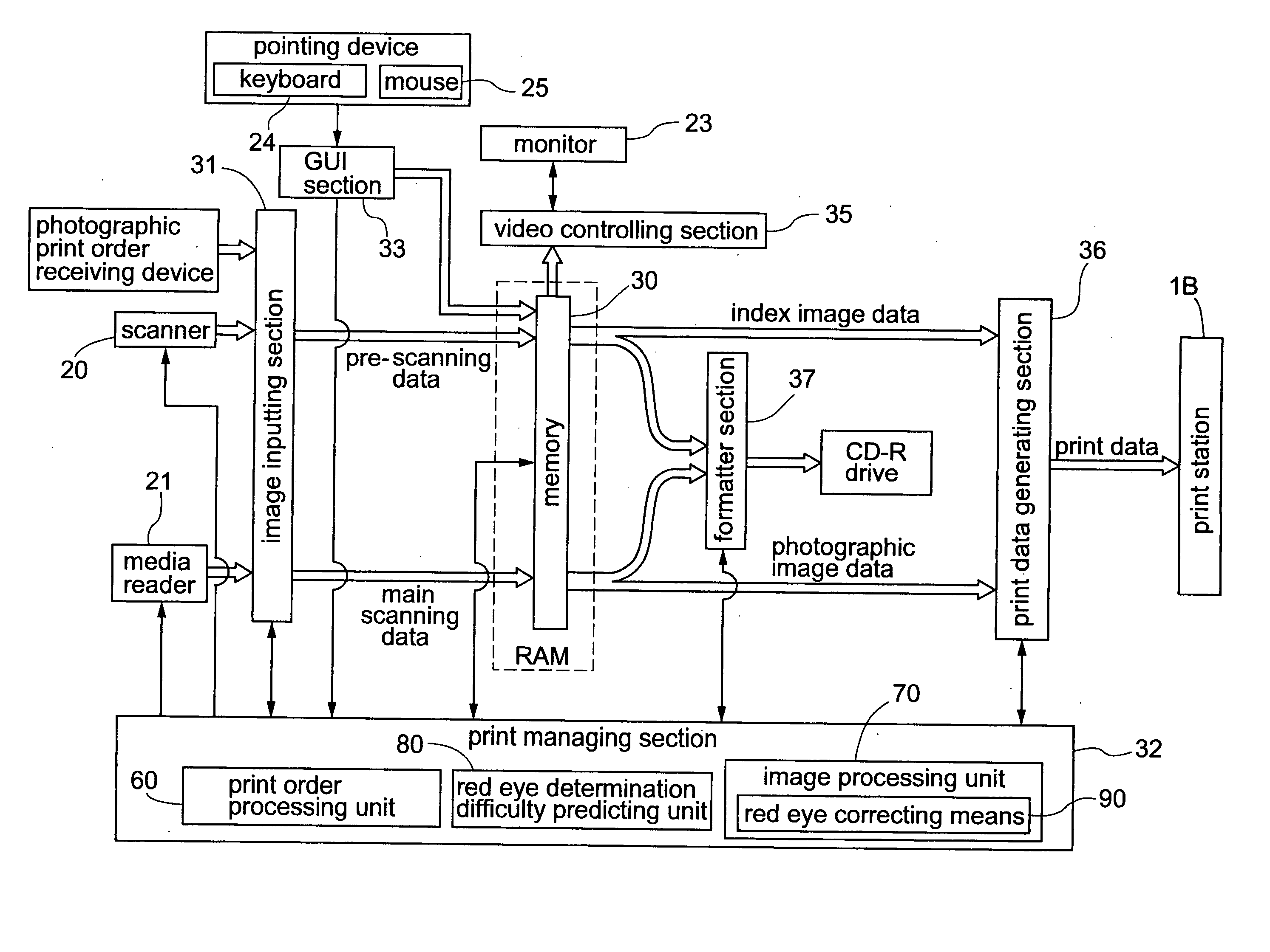
[0007] In view of the above-described state of the art, a primary object of the present invention is to provide an improved red eye correction technique with sufficient reliability without using any complicated image processing technique such as pattern recognition and without requiring any preparatory operation such as designation of an eye area.
[0014] According to this red eye correcting method proposed by the present invention, from the entire photographic image, skin color pixels, white color pixels and red color pixels are detected respectively based on the predetermined detection condition individually set therefor. Each detected red color pixel is set as a red eye pixel candidate. Then, based on the respective total numbers of the skin color pixels and the white color pixels present within the area around the red eye pixel candidate, it is determined whether the peripheral area of the red eye pixel candidate is en eye area or not and also whether this red eye pixel candidate actually is a red eye pixel constituting the red eye phenomenon or not. In this way, a red eye pixel is determined, based on distribution conditions of skin, white and red colors which together characterize the tone of a red eye area. Hence, as compared with the conventional red eye detection techniques described above, the invention's method allows red eye pixel detection with satisfactory reliability, with a simple algorithm, yet without requiring any preparatory operation such as the advance designation of an eye area.
[0017] In either case, depending on a photographic subject, other than its eye area, there can occur an area with similar distributions of white, skin and red color components to those of the eye area. This can result in an error in the recognition of the red eye pixel. If such red eye like pixel is strongly corrected, the resultant print will appear unnatural. Therefore, if it is possible to predict difficulty in the red eye determination based on e.g. the photographic condition, it will be useful if the degree of the red eye correction is adjusted according to the predicted difficulty in the red eye determination. For instance, in the case of a photography under a special illumination, the distinction between the respective colors becomes difficult. In such case, the degree (intensity) of the red eye correction may be reduced to a half or less, so that the correction will not result in disturbance in the total color balance even if erroneous recognition occurs.

Problems solved by technology

However, this technique is unpopular since this is extremely troublesome and requires high skill on the part of the artisan.
In this case, however, for precise detection of red eye area, very complicated image processing technique is required and also the system implementing the technique tends to be very expensive.
Moreover, as this conventional technique requires designation of the eye area in advance, for realizing its full automization, a new technology will be needed for image recognition of the eye area, which technology is difficult to achieve.
However, as this technique recognizes a red eye portion based on the skin color and the red color, an erroneous recognition tends to occur.

Method used


Image

  • Image processing method and appparatus for red eye correction
  • Image processing method and appparatus for red eye correction
  • Image processing method and appparatus for red eye correction

Examples


Embodiment Construction

[0037] Preferred embodiments of the present invention will be described in details with reference to the accompanying drawings.

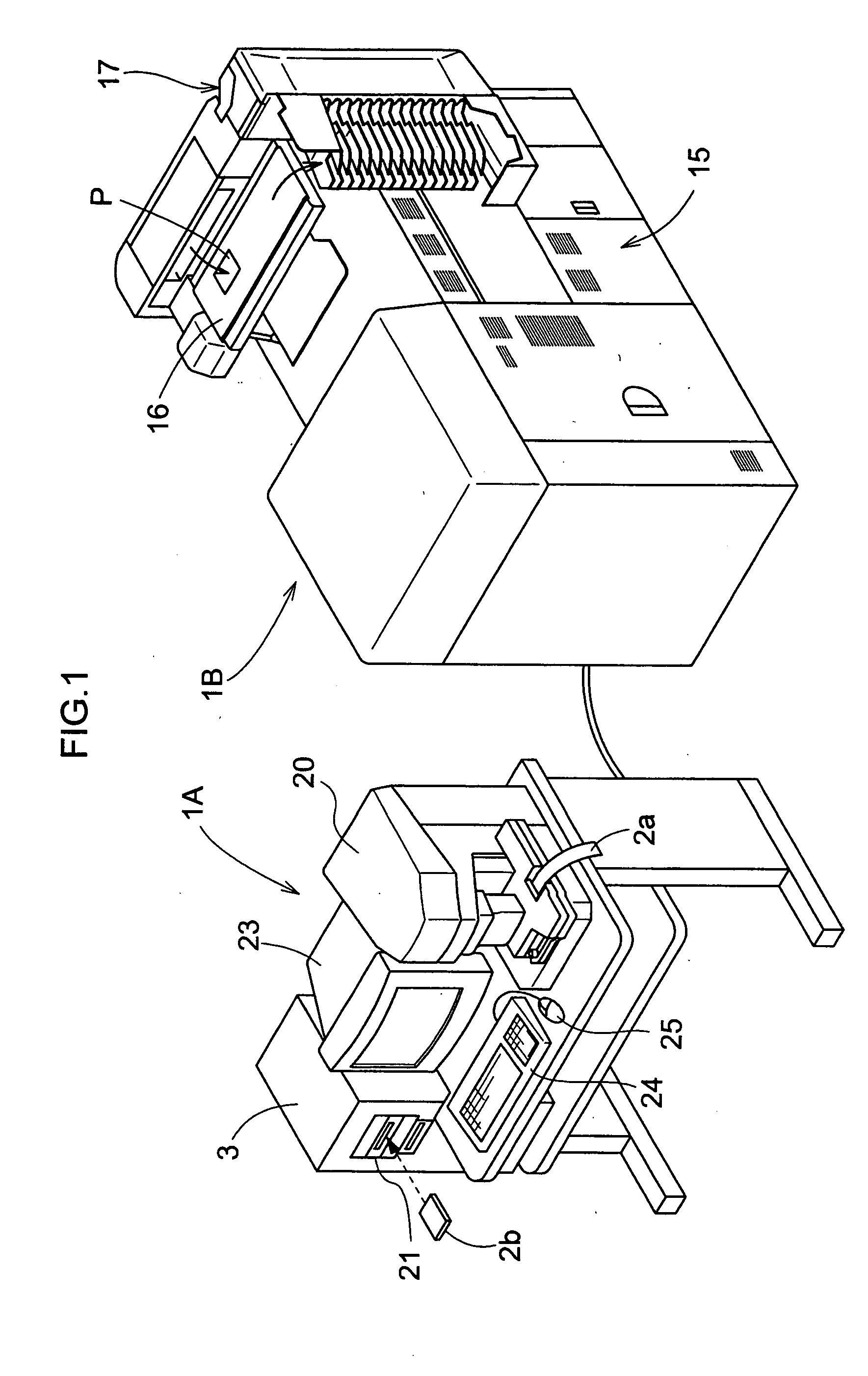
[0038]FIG. 1 shows an outer appearance of a photographic printing system employing the red eye correction technique of the present invention. As shown, this printing system consists mainly of a printing station 1B as a photographic printer for effecting exposure and development on a print paper P and an operating station 1A for processing photographic images taken from a developed photographic film 2a or various image input media such as a memory card 2b for a digital camera and effecting production / transmission of print data to be used in the printing station 1B.

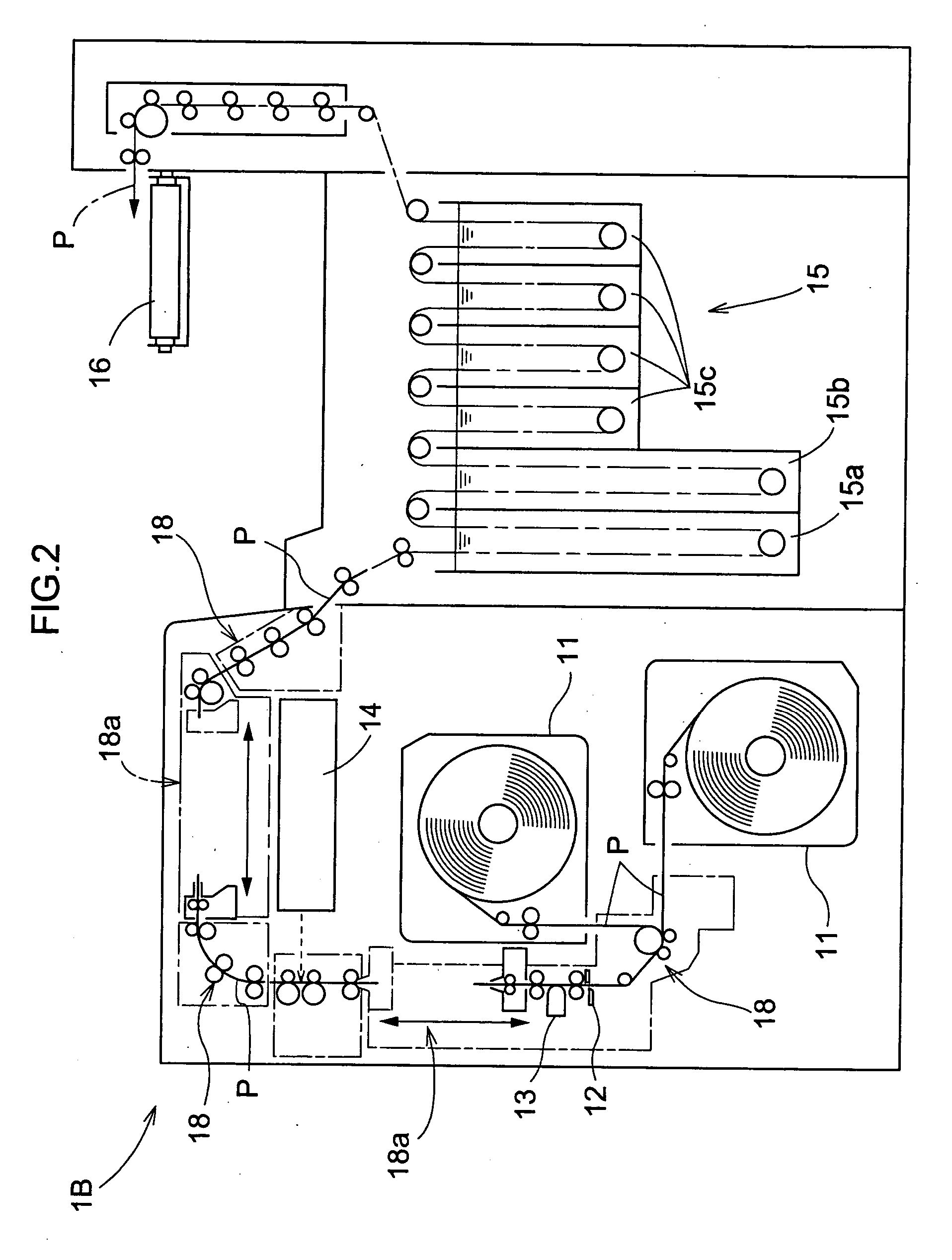
[0039] This photographic printing system is known also as “digital mini-labo”. As best understood from FIG. 2, in the printing station 1B, a print paper P stored in the form of a roll in either one of two print paper magazines 11 is drawn out and cut by a sheet cutter 12 to a print size strip. On ...


PUM


Abstract

An image processing apparatus for correcting red eye phenomenon in photographic image data. This apparatus includes a skin color pixel detecting portion for detecting a skin color pixel in the image data based on a predetermined skin color detection condition, a white color pixel detecting portion for detecting a white color pixel in the image data based on a predetermined white color detection condition, a red color pixel detecting portion for detecting a red color pixel in the image data based on a predetermined red color detection condition, a red eye pixel determining section for setting the detected red color pixel as a red eye pixel candidate and then determining the red eye pixel candidate as a red eye pixel according to a determination condition using the number of the skin color pixels and the number of the white color pixels detected respectively within an area around the red eye pixel candidate and a red eye correcting section for correcting the red eye phenomenon by changing a pixel value of the determined red eye pixel.

Description

BACKGROUND OF THE INVENTION [0001] 1. Field of the Invention [0002] The present invention relates to an image processing method for correcting a red eye phenomenon occurring in photographically recorded image data and relates also to an apparatus for implementing this method. [0003] 2. Description of the Related Art [0004] In flash pictures of such subject as a human or an animal, there can occur a so-called red eye phenomenon resulting from reflection of the flash light off the blood vessels of the retina of the subject's eyes, causing the center of the pupils of the eyes to appear red or in a color different from the actual color thereof. With ever increasing popularity of digital cameras as well as film scanners for digitizing photographic image of a photographic film, various and numerous solutions have been proposed to tackle this problem by means of image processing technique. Of course, correction of red eye phenomenon is possible by a professional technique in which a skille...

Claims


Application Information

Patent Timeline
IPC IPC(8): B41J1/00G03B27/72G06K9/00G06T1/00G06T5/00G06T7/00G06T7/40H04N1/46H04N1/60H04N1/62H04N9/74
CPCG06K9/0061H04N1/624G06T2207/30216G06T7/408G06T7/90G06V40/193
Inventor KUGO, KOICHI
Owner NK WORKS CO LTD
Learn More