X-ray tube system and apparatus with conductive proximity between cathode and electromagnetic shield

a technology of x-ray tubes and electromagnetic shields, applied in the direction of x-ray tubes, x-ray tube cathode assemblies, nuclear engineering, etc., can solve the problems of cracking of insulators, air leakage, etc., and achieve the effect of preventing bending of electrostatic field lines

Inactive Publication Date: 2005-06-02
GE MEDICAL SYST GLOBAL TECH CO LLC
View PDF5 Cites 9 Cited by
  • Summary
  • Abstract
  • Description
  • Claims
  • Application Information

AI Technical Summary

Benefits of technology

[0010] The present invention provides an imaging tube that includes a vacuum vessel and an atmospheric-side supply line assembly. The vacuum vessel has an internal vacuum. The supply line assembly has an electromagnetic shield. An insulator separates the internal vacuum from an external atmosphere. A cathode post resides within the vacuum vessel. The cathode post is in conductive proximity with the electromagnetic shield and prevents bending of electrostatic field lines within the imaging tube.
[0011] The embodiments of the present invention provide several advantages. One such advantage provided by multiple embodiments of the present invention is the provision of configuring an x-ray tube such that a cathode post is in conductive proximity with an electromagnetic shield of a high-voltage supply line assembly. In so doing, the stated embodiments prevent bending of electrostatic field lines within the x-ray tube. Prevention of the electrostatic field lines prevents arcing and breakdown of a high-voltage x-ray tube insulator, thus increasing life of the x-ray tube.
[0012] Furthermore, the present invention increases high-voltage stability of an x-ray tube, which in turn minimizes the manufacturing time of the x-ray tube. A decrease in the manufacturing time results in a reduction in x-ray tube cost and cycle time. The present invention increases ease in discriminating between a high-voltage stable tube and an unstable tube, such as a tube with contamination, insufficient exhaust or seasoning, loose foreign material, or a tube having surface contaminating films; all of which can compromise the high-voltage stability or performance of an x-ray tube.

Problems solved by technology

Many of the test protocols and calibration procedures are more aggressive than the typical or anticipated protocols and procedures in actual endpoint customer use.
The arcing can damage, breakdown, and cause cracking of the insulator.
Breakdown of the insulator can eventually cause air leaks and render the x-ray tube inoperable.
The arcing can also result in atmosphere side flashovers, which can cause damage to other x-ray system componentry.

Method used


Image

  • X-ray tube system and apparatus with conductive proximity between cathode and electromagnetic shield
  • X-ray tube system and apparatus with conductive proximity between cathode and electromagnetic shield
  • X-ray tube system and apparatus with conductive proximity between cathode and electromagnetic shield

Examples


Embodiment Construction

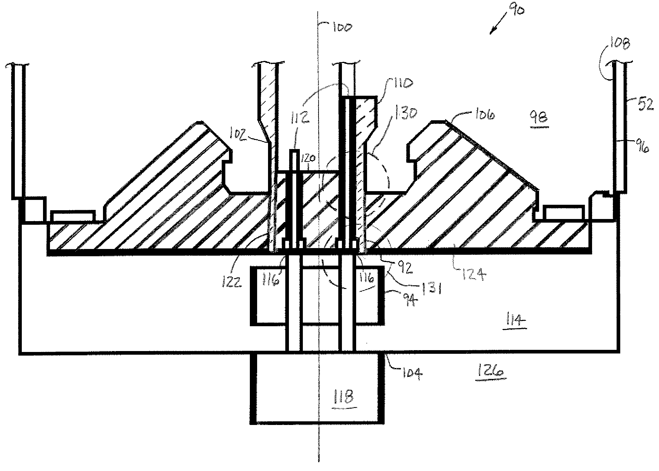
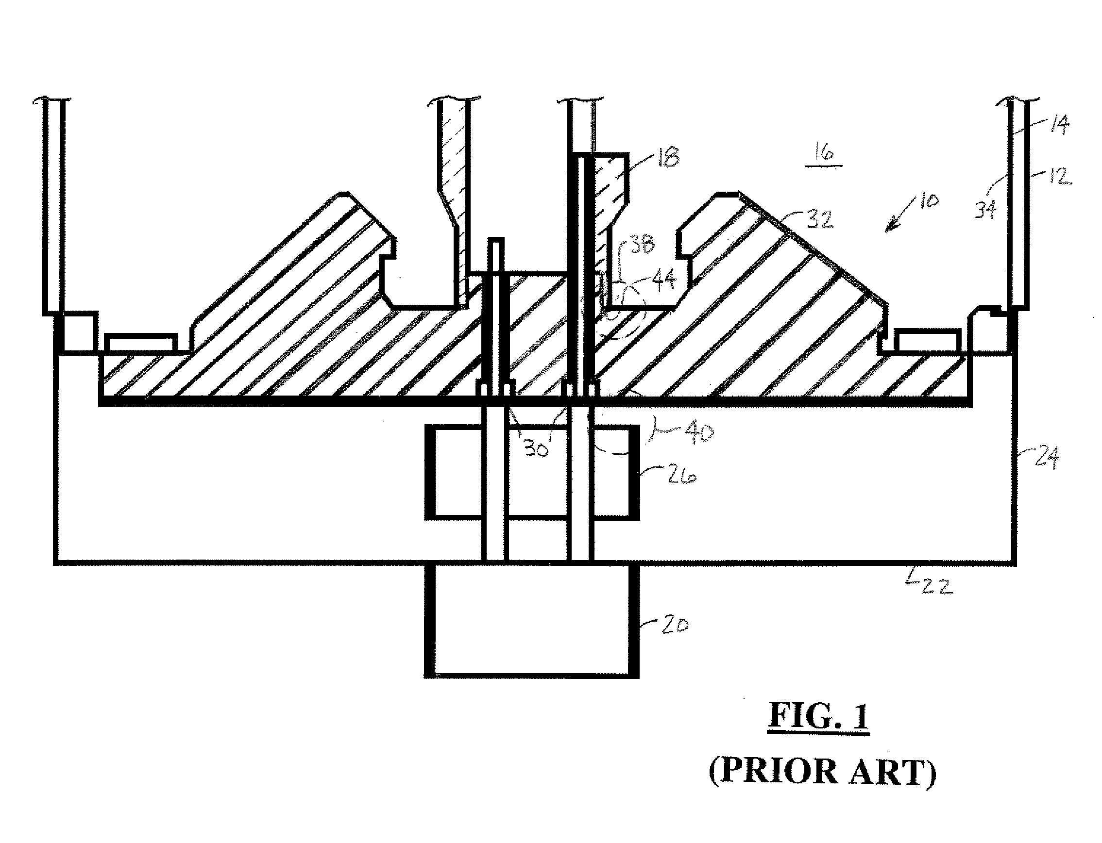
[0023] Referring now to FIG. 1, a close-up cross-sectional view of a high-voltage insulator portion 10 of a traditional x-ray tube 12 is shown. The x-ray tube 12 has a vacuum vessel 14 with an internal vacuum 16. A cathode post 18 resides within the vacuum 16 and receives power from a high-voltage cable 20 via a high-voltage connector assembly 22. The connector assembly 22 includes a main connector 24 that is coupled to the vacuum vessel 14 and a Faraday cage 26. The Faraday cage 26 provides an electromagnetic shield around and prevents breakdown of connector connections 30.

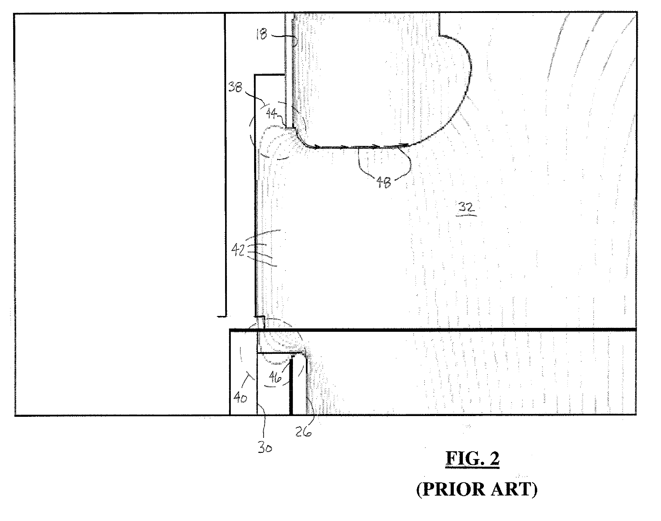
[0024] A high-voltage insulator 32 is coupled between the cathode post 18 and walls 34 of the vacuum vessel 14, and along side the connector assembly 22. Notice that the cathode post 18 and the Faraday cage 26 are separated by the insulator 32 and the connector 24. A triple point area exists at a connection 44 between the cathode post 18 and the insulator 32 near the vacuum 16. A high field stress area exists in...


PUM


Abstract

An imaging tube (52, 52′) includes a vacuum vessel (96) and an atmospheric-side supply line assembly (104, 104′). The vacuum vessel (96) has an internal vacuum (98). The supply line assembly (104, 104′) has an electromagnetic shield (94, 94′). An insulator (106, 106′) separates the internal vacuum (98) from an external atmosphere (126). A cathode post (92, 92′) resides within the vacuum vessel (96). The cathode post (92, 92′) is in conductive proximity with the electromagnetic shield (94, 94′) and prevents the bending of electrostatic field lines within the imaging tube (52, 52′).

Description

BACKGROUND OF INVENTION [0001] The present invention relates generally to the high-voltage stability of computed tomography x-ray sources. More particularly, the present invention relates to the minimization of electrostatic field line bending within the triple point areas of an x-ray tube. [0002] High-voltage stability of high power and high-voltage computed tomography (CT) x-ray sources, such as an x-ray tube, is essential to constructing, seasoning, testing, and placing of the x-ray sources in service. During manufacturing of an x-ray tube, the x-ray tube is assembled and tested. Following the manufacturing of the x-ray tube, the x-ray tube is further tested and calibrated during system assembly. Many of the test protocols and calibration procedures are more aggressive than the typical or anticipated protocols and procedures in actual endpoint customer use. A desire to withstand the rigorous protocols and procedures in addition to a desire for the quick and efficient execution th...

Claims


Application Information

Patent Timeline
Patent Type & Authority Applications(United States)
IPC IPC(8): G21G4/00H01J35/00H01J35/04H01J35/06H01J35/16H01J35/20H01L35/02H05H1/00
CPCH01J35/06H01J35/165H01J2235/166H01J2235/06H01J2235/023H01J35/16
Inventor TEKLETSADIK, KASEGNPRICE, JOHN SCOTT
Owner GE MEDICAL SYST GLOBAL TECH CO LLC
Why Eureka
Try Eureka