Intervertebral bone fusion device

a bone fusion and vertebral technology, applied in the field of surgical methods and devices to treat back and leg pain, can solve the problems of nerve dysfunction and debilitating back pain, and achieve the effects of preventing subsidence lordosis, facilitating bone graft application, and convenient direction

Inactive Publication Date: 2005-06-02
LAWSON INC
View PDF8 Cites 113 Cited by
  • Summary
  • Abstract
  • Description
  • Claims
  • Application Information

AI Technical Summary

Benefits of technology

[0011] An advantage of the present invention is that the device comprises head-tail (cephalad-caudad) with tapering posterior so that the back of the polygon is narrower than the front. This gives greater support anterior to load in preventing subsidence lordosis.
[0012] Another advantage of the present invention is that it provides ease of application of bone grafts. Such as for impaction of cancellous bone grafts after placement of the device and narrow posterior aspect easily direc...

Problems solved by technology

A damaged disc can cause nerve dysfunction and debil...

Method used


Image

  • Intervertebral bone fusion device
  • Intervertebral bone fusion device
  • Intervertebral bone fusion device

Examples


Embodiment Construction

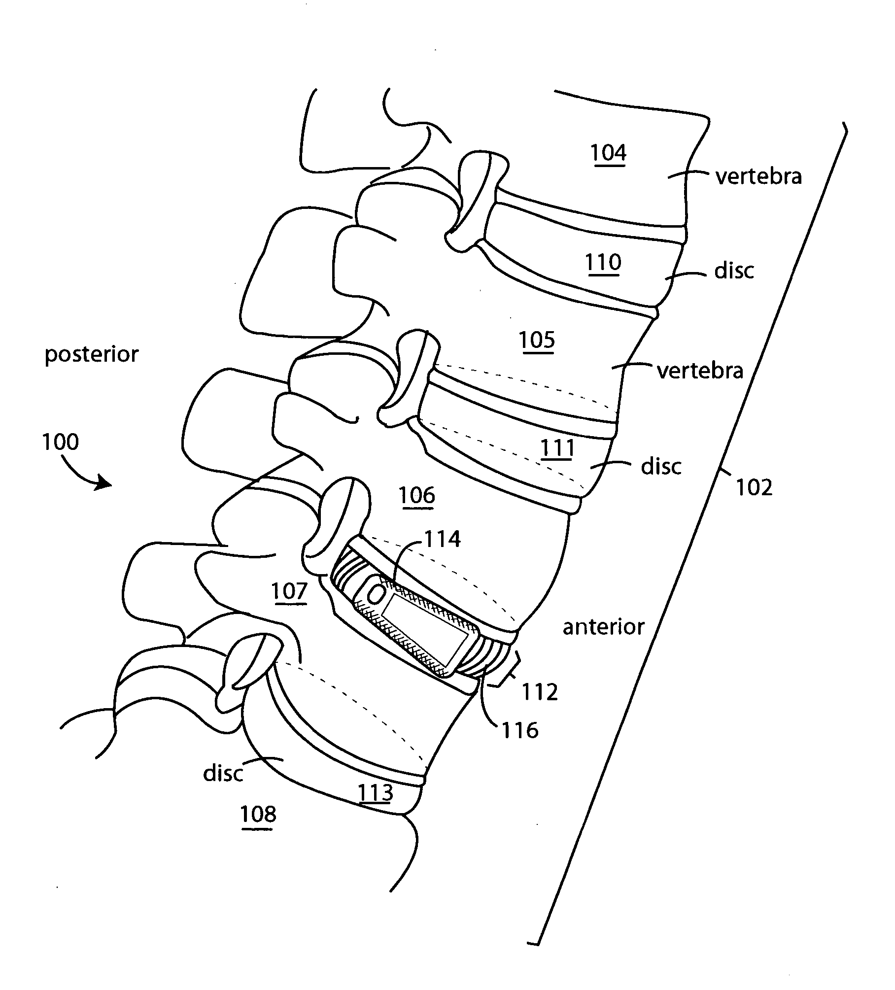
[0018]FIG. 1 illustrates the placement of a surgical implant embodiment of the present invention, referred to herein by the reference numeral 100. A human spine 102 commonly comprises a series of vertebrae 104-108 interdigitated with a corresponding series of discs 110-113. Each natural disc comprises a nucleus pulposus surrounded and contained by a corresponding annulus fibrosis. Natural nucleus pulposus have jelly-like structures that can absorb and dampen compressive shock loads. Natural annulus fibrosis structures comprise multiple layers of bias-ply filaments set at forty-degree angles that resemble the construction of an automobile bias-ply tire carcass.

[0019] Disc 112, between vertebra 106 and 107, is assumed in FIG. 1 to be degenerated. A surgical implant embodiment of the present invention, referred to herein by reference numeral 114, is surgically embedded in the inter-vertebral space between vertebra 106 and 107, and inside an annulus fibrosis 116.

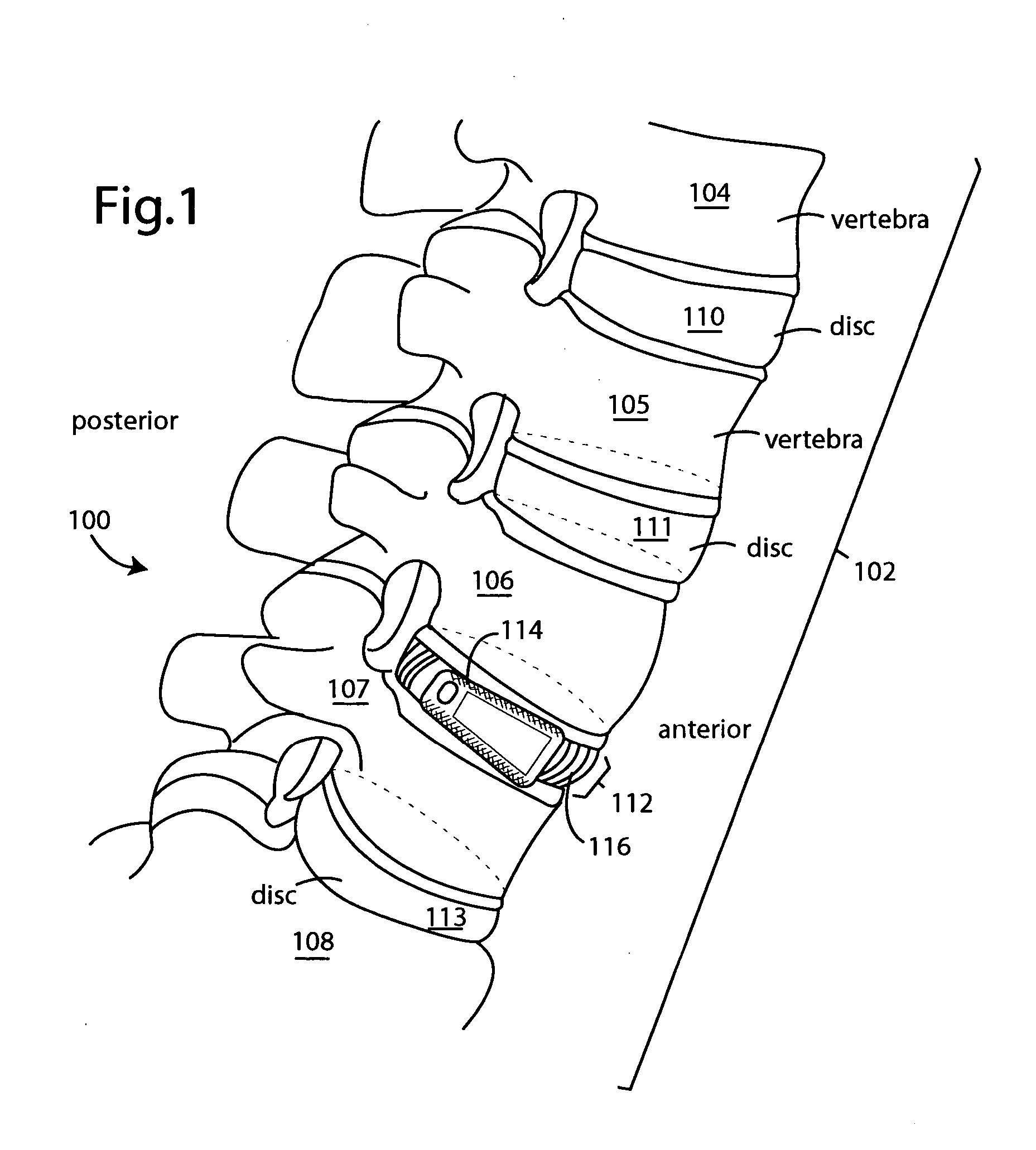
[0020]FIG. 2 represent...


PUM


Abstract

A surgical spine implant comprises a solid wedge shape device body is such that said polygonal shape with decreased height posterior and several surfaces that contours to the anatomy of the spine intervertebral space without complex machining across radiuses. The diminished height posteriorly provides for the angulations necessary to accommodate and ensure maintenance of the normal spinal alignment resulting in posterior extension angulations. The device provides ease of application of bone grafts. Such as for impaction of cancellous bone grafts after placement of the device and narrow posterior aspect easily directs grafts. This minimizes the problem of bone grafts hanging up behind the device either to the right or the left of the medial or lateral, which prevents the displacement of the device or prominence of the bone grafts near the spinal canal. The recess hole in the device accommodates a holding insertion tool and ease of bone graft packing “fill” to ensure a tight fit and immobile the attachment of the disc to the lower vertebrae.

Description

BACKGROUND OF THE INVENTION [0001] 1. Field of the Invention [0002] The present invention relates to surgical methods and devices to treat back and leg pain, and in particular to the surgical insertion of devices that immobilize and promote bone growth within the annulus fibrosis between adjacent vertebrae. [0003] 2. Description of Related Art [0004] In the spine, the principal function of the disco-vertebral joint is to transmit compressive loads while allowing flexibility. The adjacent vertebrae are joined with a triple-joint complex. The vertebral bodies form the anterior complex or column. These are shaped like flattened cylinders with disc shaped or oval shaped. The intervertebral discs are sandwiched between each vertebrae. The facet joints in the rear of each vertebrae have a smooth cartilage surface, lubricating joint fluid, and a cover. The facet joints restrict the disc for small degrees of flexion and extension, limit rotation, and protect against translational shear stre...

Claims


Application Information

Patent Timeline
IPC IPC(8): A61B17/88A61F2/28A61F2/30A61F2/44A61F2/46
CPCA61F2/4455A61F2/4611A61F2002/2835A61F2002/4628A61F2002/448A61F2002/4622A61F2002/30772
Inventor LAWSON, KEVIN JON
Owner LAWSON INC
Why Eureka
Try Eureka