Low profile plastic panel enclosure

a plastic panel and enclosure technology, applied in special buildings, parkings, buildings, etc., can solve the problems of inability to form blow molded plastic components with intricate shapes and/or sharp corners required for integrated connectors, inability to meet the longfelt needs of consumers for structural integrity, aesthetic appearance, and modularity, and achieve easy and reliable access.

Inactive Publication Date: 2005-06-09
SUNCAST
View PDF26 Cites 26 Cited by
  • Summary
  • Abstract
  • Description
  • Claims
  • Application Information

AI Technical Summary

Benefits of technology

[0010] The present invention provides a system, or kit, of injection molded panels having integrated connectors which combine to form an enclosure, commonly in the form of a low profile utility enclosure. The enclosure is provided with a telescoping roof panel and pivoting doors which allow easy and dependable access to the interior of the enclosure. The system incorporates a minimum number of components to construct a low profile enclosure by integrally forming connectors into injection molded panels. The panels utilized to construct the low profile enclosure are formed of injection molded plastic and include sockets which accept both roof and floor locking posts for interlocking cooperative engagement which serves to rigidly connect the components together.

Problems solved by technology

During the off-seasons, lawn mowers, tillers and snow equipment often consume the available floor space of a garage, forcing the homeowner to park his / her automobile outside.
Due to the nature of the manufacturing process, blow molded plastic components cannot be formed with the intricate shapes and / or sharp corners required for integrated connectors.
In addition, blow molded plastic components are hollow and cannot be formed with the integral strengthening ribs and gussets possible with injection molding.
Such prior art enclosure systems, while functional, nevertheless fail to meet longfelt needs of consumers to provide structural integrity combined with modularity and aesthetic appearance.
The walk-in structures may be undesirable or unsightly where the roofs are visible over neighborhood fences or hedges.
In some areas homeowner associations may not permit structures having an adequate height to allow the owner to walk into the enclosure due to the unsightly nature of the visible roof tops.
There are also commercial considerations that must be satisfied by any viable low profile enclosure system or kit; considerations which are not entirely satisfied by state of the art products.

Method used


Image

  • Low profile plastic panel enclosure
  • Low profile plastic panel enclosure
  • Low profile plastic panel enclosure

Examples


Embodiment Construction

[0040] While the present invention is susceptible of embodiment in various forms, there is shown in the drawings and will hereinafter be described a presently preferred embodiment with the understanding that the present disclosure is to be considered an exemplification of the invention and is not intended to limit the invention to the specific embodiments illustrated.

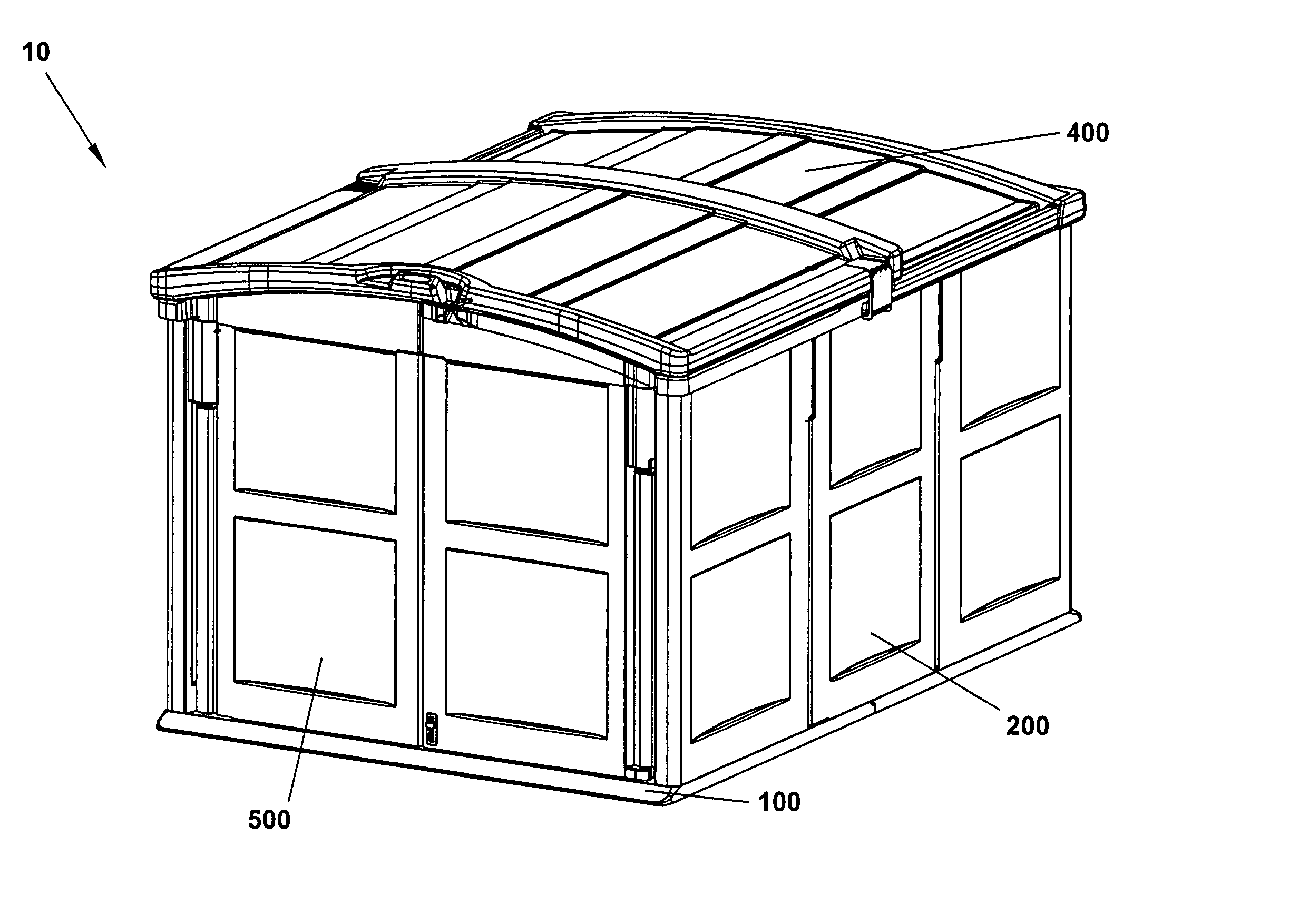
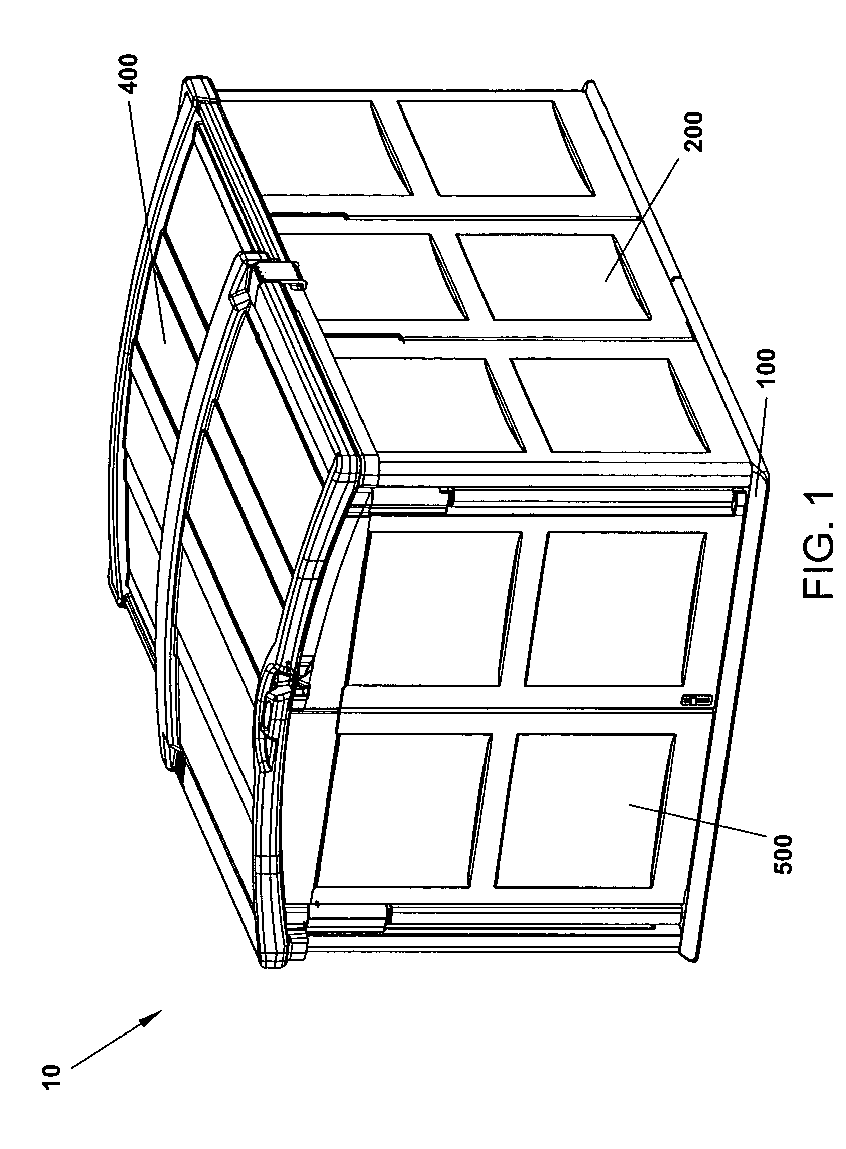
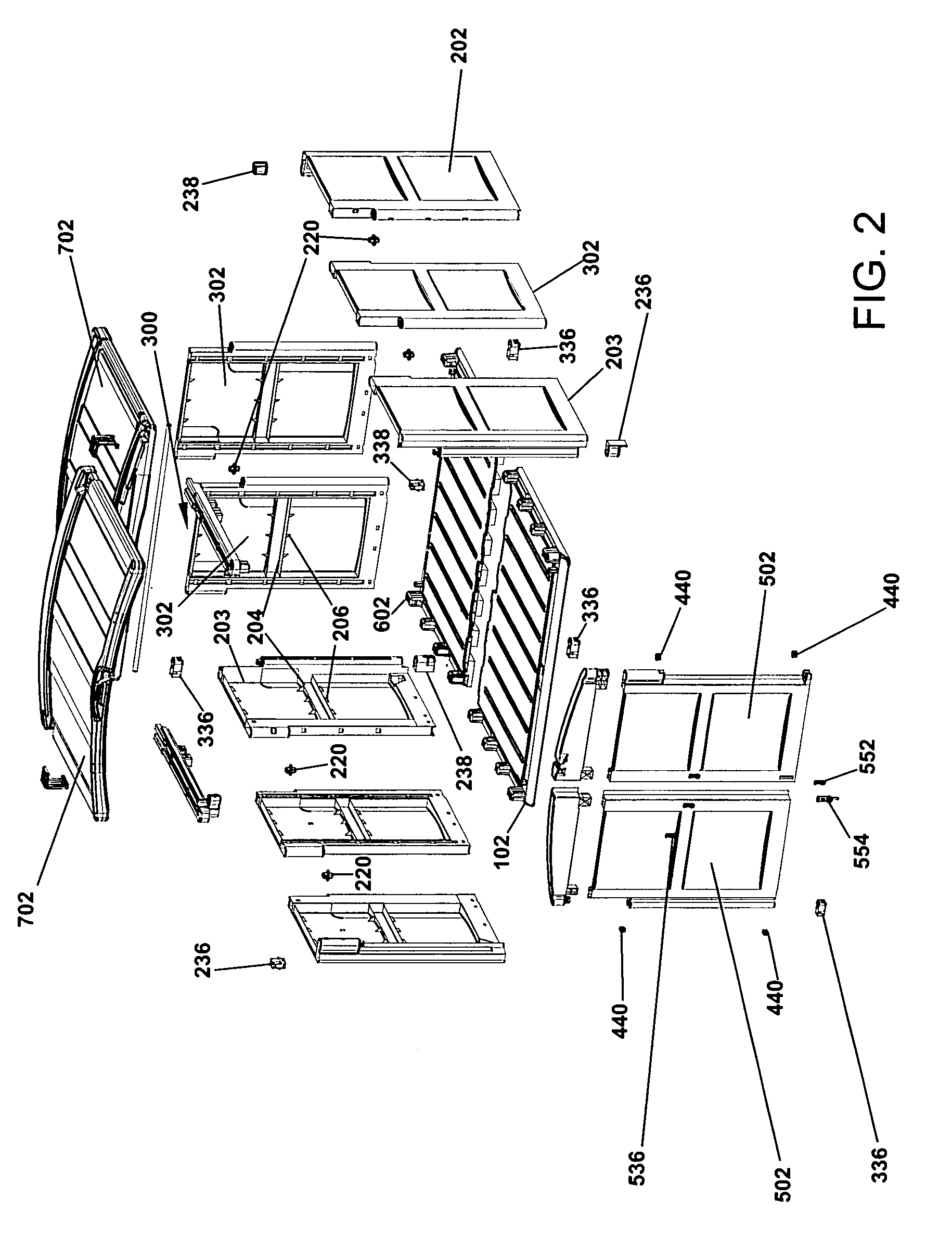
[0041]FIGS. 1 and 2 which are now referenced show an isometric and exploded view of the low profile enclosure, generally referenced as 10, according to a preferred embodiment of the present invention. The enclosure is made up of a floor assembly 100, left and right side wall assemblies 200, rear wall assembly 300 (FIG. 2), roof assembly 400 and door assembly 500. In the preferred embodiment, the panels comprising the assemblies are formed of, but not limited to, a suitable polymeric material through the process of injection molding. The result is that the panels comprising the floor 100, walls 200-300, roof 400, and do...


PUM


Abstract

The present invention provides a system of injection molded panels having integrated connectors which combine to form a low profile enclosure having a telescoping roof. The panels are formed of injection molded plastic to interlock with one another without the need for separate I-beam connectors. The ends of the wall panels have cavities to accept both roof and floor outwardly projecting locking posts for interlocking cooperative engagement which serve to rigidly connect the components together. The construction of the wall, roof, floor and door components minimizes component shapes and simplifies enclosure construction.

Description

FIELD OF THE INVENTION [0001] This invention relates generally to a low profile enclosure constructed of plastic structural panels. More specifically, the present invention relates to a low profile enclosure which includes telescoping roof panels. BACKGROUND INFORMATION [0002] Storage sheds are a necessity for lawn and garden care, as well as general all-around home storage space. Typically, garden tools and equipment are found either stacked into a corner of the garage, or bundled together and covered with a tarpaulin to protect them from the elements. During the off-seasons, lawn mowers, tillers and snow equipment often consume the available floor space of a garage, forcing the homeowner to park his / her automobile outside. [0003] The prior art has proposed a number of different panel systems, or kits comprising blow molded or extruded panels and connector members for forming a wide variety of structures. Typically such systems are assembled into structures having a height sufficie...

Claims


Application Information

Patent Timeline
Patent Type & Authority Applications(United States)
IPC IPC(8): E04B1/343E04H1/12
CPCE04H1/1205E04B1/34321
Inventor WHITEHEAD, STEVENUFFNER, MICHAEL
Owner SUNCAST
Why Eureka
Try Eureka