Transcritical heat pump water heating system using auxiliary electric heater

Inactive Publication Date: 2005-06-09
CARRIER CORP
View PDF4 Cites 11 Cited by
  • Summary
  • Abstract
  • Description
  • Claims
  • Application Information

AI Technical Summary

Benefits of technology

[0012] The auxiliary electric heater can also be located on the refrigerant line proximate to the compressor discharge. In this example, the auxiliary electric heater can also decrease the time of the defrost cycle. When the surface temperature of the evaporator is below the dew-point temperature of the moist outdoor air, water dr

Problems solved by technology

Chlorine containing refrigerants have been phased out in most of the world due to their ozone destroying potential.
In the prior art, the vapor compression system is oversized to provide enough heat

Method used


Image

  • Transcritical heat pump water heating system using auxiliary electric heater
  • Transcritical heat pump water heating system using auxiliary electric heater
  • Transcritical heat pump water heating system using auxiliary electric heater

Examples


Embodiment Construction

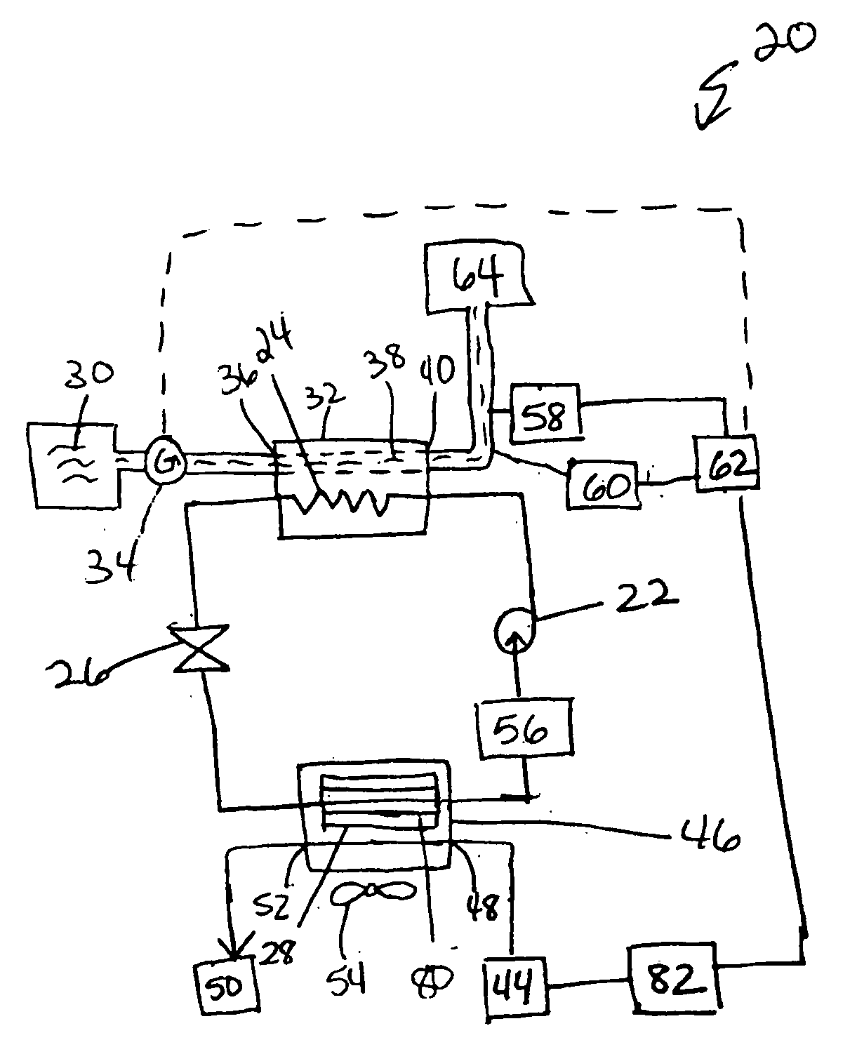
[0018]FIG. 1 illustrates an example vapor compression system 20 that includes a compressor 22, a heat rejecting heat exchanger (a gas cooler in transcritical cycles) 24, an expansion device 26, and a heat accepting heat exchanger (an evaporator) 28. Refrigerant circulates through the closed circuit system 20.

[0019] The refrigerant exits the compressor 22 at a high pressure and a high enthalpy. The refrigerant then flows through the gas cooler 24 at a high pressure. A fluid medium 30, such as water or air, flows through a heat sink 32 of the gas cooler 24 and exchanges heat with the refrigerant flowing through the gas cooler 24. In the gas cooler 24, the refrigerant rejects heat into the fluid medium 30, and the refrigerant exits the gas cooler 24 at a low enthalpy and a high pressure. A water pump 34 pumps the fluid medium through the heat sink 32. The cooled fluid medium 30 enters the heat sink 32 at the heat sink inlet or return 36 and flows in a direction opposite to the directi...


PUM


Abstract

Refrigerant is circulated through a vapor compression system including a compressor, a gas cooler, an expansion device, and an evaporator. An auxiliary electric heater is activated to further heat the heated water exiting the gas cooler when the heating capacity of the system is low. The auxiliary electric heater can be located on the water line exiting the gas cooler, in a water tank that stores the heated water, or on the refrigerant line proximate to the compressor discharge.

Description

BACKGROUND OF THE INVENTION [0001] The present invention relates generally to a transcritical vapor compression system including an auxiliary electric heater that further heats the water that exchanges heat with the refrigerant in the gas cooler. [0002] Chlorine containing refrigerants have been phased out in most of the world due to their ozone destroying potential. Hydrofluoro carbons (HFCs) have been used as replacement refrigerants, but these refrigerants still have high global warming potential. [0003]“Natural” refrigerants, such as carbon dioxide and propane, have been proposed as replacement fluids. Carbon dioxide can be used as a refrigerant in automotive air conditioning systems and other heating and cooling applications. Carbon dioxide has a low critical point, which causes most air conditioning systems utilizing carbon dioxide as a refrigerant to run transcritically, or partially above the critical point, under most conditions. [0004] A vapor compression system usually op...

Claims


Application Information

Patent Timeline
IPC IPC(8): F25B9/00F25B30/02F25D21/08
CPCF25B9/008F25B30/02F25B2309/061F25B2339/047F25B2600/13Y02B30/745F25B2700/2106F25B2700/2111F25B2700/21161F25D21/08F25B2700/11B60H2001/00961Y02B30/70
Inventor ZHANG, LILICHEN, YU
Owner CARRIER CORP
Why Eureka
Try Eureka