Apparatus and method for reducing electrical noise in a thermally controlled chuck

a technology of electrical noise reduction and thermal control, which is applied in the field of apparatus and methods for reducing electrical noise in thermal control chucks, can solve the problems of degrading the performance accuracy of testing, one source of electrical noise, and continuing to decrease the cost of individual integrated circuit chip dies in comparison to ic package costs, so as to achieve the effect of reducing the electrical noise introduced by the fluid and carrying out more accurately

Inactive Publication Date: 2005-06-09
TEMPTRONIC
View PDF26 Cites 6 Cited by
  • Summary
  • Abstract
  • Description
  • Claims
  • Application Information

AI Technical Summary

Benefits of technology

[0014] In one embodiment, a first valve is connected in the first fluid carrying path, and a second valve is connected in the second fluid carrying path. The first and second valves are closed when the temperature of the chuck is above a predetermined temperature, e.g., the boiling temperature of the temperature control fluid, such that the temperature control fluid is prevented from flowing into the chuck.
[0015] The various techniques of the invention result in controlling flow and other behavior of the temperature control fluid used to control temperature in a chuck. The result is that electrical noise introduced by the fluid is reduced, and, accordingly, wafer processing such as prober testing over temperature, can be carried out more accurately.

Problems solved by technology

In the semiconductor integrated circuit industry, the cost of individual integrated circuit chip die is continuing to decrease in comparison to IC package costs.
In some applications, such as where a wafer is being tested on a circuit prober, the presence of electrical noise in the system can degrade the performance accuracy of the testing.
One source of electrical noise is the temperature control fluid that circulates through the chuck.
The motion and other behavior of the fluid in the chuck or in the lines carrying the fluid to and from the chuck can create electrical noise by triboelectric effects whereby electrical charge is produced by friction between two objects.

Method used


Image

  • Apparatus and method for reducing electrical noise in a thermally controlled chuck
  • Apparatus and method for reducing electrical noise in a thermally controlled chuck
  • Apparatus and method for reducing electrical noise in a thermally controlled chuck

Examples


Embodiment Construction

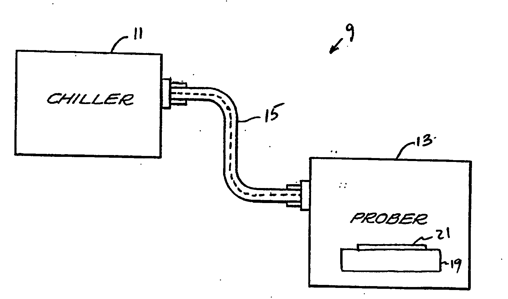
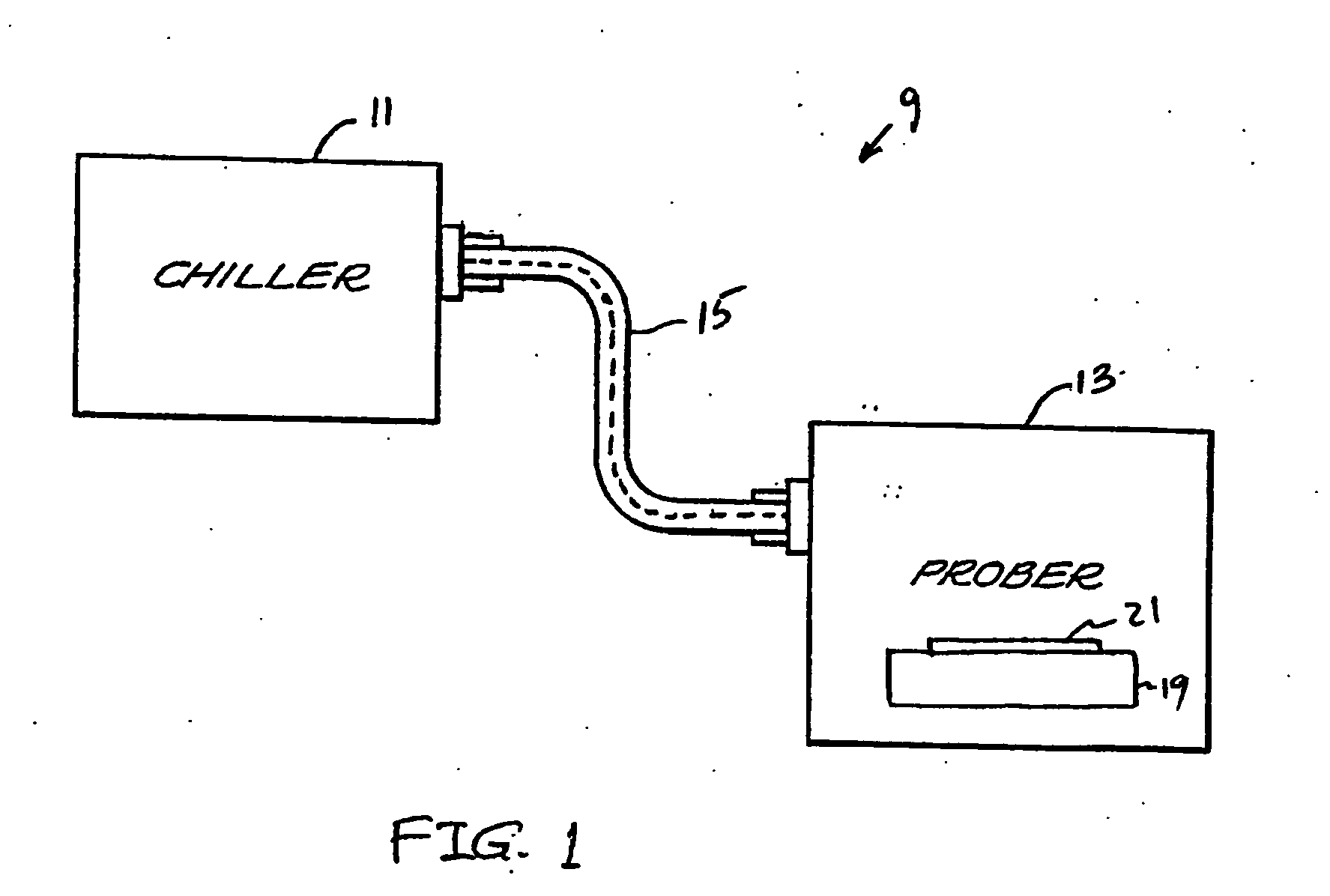
[0020]FIG. 1 contains a top-level schematic block diagram of a temperature control system and workpiece chuck connected to control temperature of a workpiece such as a semiconductor wafer mounted on the workpiece chuck. The system 9 includes a temperature control system such as a chiller 11, which controls the temperature of a temperature control fluid. The chiller 11 can be of the type manufactured and sold by Temptronic Corporation of Sharon, Mass., the assignee of the present application. Specifically, the chiller can be a Model Number TP03500A Atlas Chiller, or similar system, which is modified to include features of the invention used to reduce electrical noise as described herein.

[0021] The temperature control fluid is routed to and from a test system, such as, for example, a wafer prober 13, along a hose or pipe 15. The hose or pipe 15 can be of the type described in U.S. Pat. No. 6,070,413, assigned to Temptronic Corporation of Sharon, Mass., and incorporated herein in its ...


PUM


Abstract

A system and method for controlling temperature of a workpiece such as a semiconductor wafer and the chuck supporting the wafer are described. The system includes a heat exchanger used in controlling temperature of a temperature control fluid. A first fluid carrying path carries the temperature control fluid from the heat exchanger to an outlet, the outlet being connectable to the workpiece chuck to carry the temperature control fluid to the workpiece chuck. A second fluid carrying path carries the temperature control fluid from an inlet to the heat exchanger, the inlet being connectable to the workpiece chuck to carry the temperature control fluid from the workpiece chuck to the temperature control system. A dual-flow rate technique is employed such that, when the chuck temperature is in transition, the temperature control fluid is circulated at a relatively high flow rate such that temperature transition of the chuck can be realized at a fast rate. When the temperature of the chuck is being maintained at a set point temperature, the flow rate of the fluid can be reduced such that electrical noise introduced by the motion of the fluid, such as by the triboelectric effect, can be reduced. A capillary tube can be connected between the first fluid carrying path and the second fluid carrying path. First and second valves can be connected in the first and second fluid carrying paths to prevent the flow of fluid into the chuck when the chuck is at high temperature such that motion induced by flash boiling of the fluid is eliminated.

Description

RELATED APPLICATION [0001] This application is based on U.S. Provisional Patent Application Ser. No. 60 / 526,030, filed on Nov. 26, 2003, the contents of which are incorporated herein in their entirety by reference.BACKGROUND OF THE INVENTION [0002] In the semiconductor integrated circuit industry, the cost of individual integrated circuit chip die is continuing to decrease in comparison to IC package costs. Consequently, it is becoming more important to perform many IC process steps while the die are still in the wafer, rather than after the relatively expensive packaging steps have been performed. [0003] Typically, in IC processing, semiconductor wafers are subjected to a series of test and evaluation steps. For each step, the wafer is held in a stationary position at a process station where the process is performed. For example, circuit probe testing is increasingly performed over a wide temperature range to temperature screen the ICs before assembly into a package. The wafer is t...

Claims


Application Information

Patent Timeline
Patent Type & Authority Applications(United States)
IPC IPC(8): H01L21/00
CPCH01L21/67248
Inventor HUDSON, DOUGLAS E.PELRIN, JAMESPATEL, SANJIVTEE, CHIN CHIENCOLE, KENNETH M. SR.
Owner TEMPTRONIC
Why Eureka
Try Eureka