Metal foil with resin and metal-clad laminate, and printed wiring board using the same and method for production thereof

a technology of metal clad laminates and metal foils, which is applied in the direction of metal layered products, metallic material coating processes, synthetic resin layered products, etc., can solve the problems of short-circuit failure, large transmission loss, and obstruct the thinning of metal foils, and achieve high reliability and circuit formability, low cost efficiency and handling

Inactive Publication Date: 2005-06-09
HITACHI CHEM CO LTD
View PDF8 Cites 110 Cited by
  • Summary
  • Abstract
  • Description
  • Claims
  • Application Information

AI Technical Summary

Benefits of technology

[0007] It is an object of the invention to provide a metal clad laminate or a resin coated metal foil in which adhesion is compatible with flatness at an interface between an insulating resin composition layer and metal foil and practical factors such as cost efficiency and handling are satisfied in manufact

Problems solved by technology

However, in practice, as described in Japanese Patent No. 2927968, a roughened layer having the thickness of several micrometers for obtaining given peel strength between the metal foil and a resin cured material is provided in the metal foil, which obstructs thinning of the metal foil.
Because of the irregularity existing in the roughened layer, an etching residue easy to generate, which causes short-circuit failure.
Further, because the irregularity of the roughened layer increases electric resistance of a conductor circuit, transmission loss becomes larger.
When the roughened layer exists in the metal foil, excessive etching is required in forming the conductor circuit, and a conductor top wid

Method used


Image

  • Metal foil with resin and metal-clad laminate, and printed wiring board using the same and method for production thereof
  • Metal foil with resin and metal-clad laminate, and printed wiring board using the same and method for production thereof
  • Metal foil with resin and metal-clad laminate, and printed wiring board using the same and method for production thereof

Examples


example 1

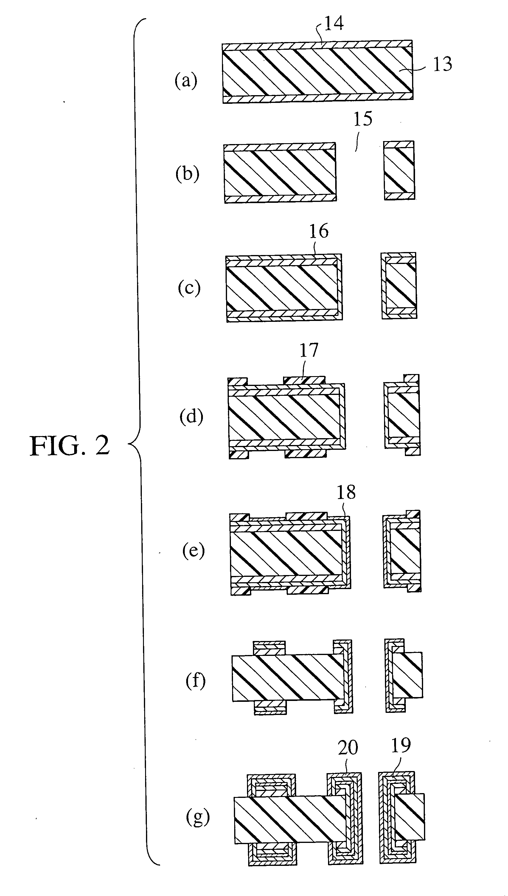
[0147] The varnish of the insulating resin composition 1 was impregnated into glass cloth (basic weight 210 g / m2) having the thickness of 0.2 mm and dried at 120° C. for 5 minutes to obtain the prepreg. The four prepregs and two pieces of the metal foil 1 were laminated while each one piece of the metal foil 1 was located at the top and the bottom. The prepreg and the metal foil were press-formed for one hour on the conditions of 170° C. and 2.45 MPa, and the carrier copper foil was peeled to manufacture the copper clad laminate including an insulating layer 13 and copper foil 14 as shown in FIG. 2(a).

[0148] As shown in FIG. 2(b), a through hole 15 having the diameter of 80 μm was made from above the metal foil with a carbon dioxide gas impact laser punching machine L-500 (product name, Sumitomo Heavy Industries, Ltd.), and a smear was removed by dipping the copper clad laminate into mixed aqueous solution of potassium permanganate of 65 g / L and sodium hydroxide of 40 g / L at a solu...

example 2

[0154] The varnish of the insulating resin composition 1 was impregnated into glass cloth (basic weight 210 g / m2) having the thickness of 0.2 mm and dried at 120° C. for 5 minutes to obtain the prepreg. The substrate was produced in a manner similar to EXAMPLE 1 except that the four prepregs and two pieces of the metal foil 2 were laminated while each one piece of the metal foil 2 was located at the top and the bottom and press-formed for one hour on the conditions of 170° C. and 2.45 MPa to manufacture the copper clad laminate shown in FIG. 2(a).

example 3

[0155] The varnish of the insulating resin composition 2 was impregnated into glass cloth (basic weight 210 g / m2) having the thickness of 0.2 mm and dried at 160° C. for 5 minutes to obtain the prepreg. The substrate was produced in a manner similar to EXAMPLE 1 except that the four prepregs and two pieces of the metal foil 2 were laminated while each one piece of the metal foil 2 was located at the top and the bottom and press-formed for one hour on the conditions of 170° C. and 2.45 MPa to manufacture the copper clad laminate shown in FIG. 2(a).


PUM

PropertyMeasurementUnit
Temperatureaaaaaaaaaa
Timeaaaaaaaaaa
Thicknessaaaaaaaaaa

Abstract

The present invention provides a metal clad laminate or a resin coated metal foil having a metal foil whose both surfaces are not substantially roughening-treated and an insulating resin composition layer using generally used insulating resin, and a printed wiring board and a manufacturing method thereof, in which the metal clad laminate or the resin coated metal foil is used, the reliability and circuit formability are high, and the conductor loss is extremely low.

Description

TECHNICAL FIELD [0001] The present invention relates to resin coated metal foil, a metal clad laminate, a printed wiring board using them, and a manufacturing method thereof. Particularly the invention relates to a technology suitable for the printed wiring board in which a conductor circuit is formed through pattern electroplating, in which metal foil of the metal clad laminate formed by fixing the metal foil onto an insulating resin composition is used as an electric power supply layer. BACKGROUND ART [0002] Recently, as demand for miniaturization, weight reduction, and speeding-up of electronic equipment is increased, density growth of the printed wiring board is in progress, and the printed wiring board manufacturing method by a semi-additive process using electroplating receives widespread attention. As described in Japanese Patent Application Laid-Open No. 11-186716, the semi-additive process is a technique in which, after a hole which becomes an interstitial via hole (hereina...

Claims


Application Information

Patent Timeline
IPC IPC(8): B32B15/08C23C28/00H05K3/38H05K3/46
CPCB32B15/08Y10T428/24917H05K3/384H05K3/389H05K3/4652Y10T428/12569Y10T428/266Y10T428/12472Y10T428/12535Y10T428/12993Y10T29/49165Y10T428/12556Y10T29/49156Y10T428/12431H05K3/382Y10T428/31522Y10T428/31529Y10T428/31605Y10T428/31663B32B15/088B32B15/092B32B27/34B32B27/38B32B2255/06B32B2255/24B32B2307/538B32B2457/08B32B15/09B32B15/20B32B27/36B32B2305/076B32B2311/12B32B2311/24B32B2369/00B32B2377/00
Inventor TAKAI, KENJISUEYOSHI, TAKAYUKI
Owner HITACHI CHEM CO LTD
Why Eureka
Try Eureka