
Simplified pipe support assembly

a pipe support and assembly technology, applied in the field of pipe supports, can solve the problems of pipe sag and be damaged, shake and rattle, addition and reworking is difficult and inconvenient, and achieves the effect of not easily reworked

Inactive Publication Date: 2005-06-09
KING ROBERT W
View PDF38 Cites 20 Cited by
  • Summary
  • Abstract
  • Description
  • Claims
  • Application Information

AI Technical Summary

Benefits of technology

[0008] Concerning installation, a length of common plastic pipe is cut to fit between 2×4 inch studs of a wall. A wall-to-pipe snap fitting is nailed or screwed to the 2×4 stud on each side of the space where a water pipe is to be mounted. The cut length of pipe is snapped into the mounted wall-to-pipe fittings. A pipe-to-pipe snap fitting is snapped onto the support pipe and the water pipe is snapped into the same pipe-to-pipe fitting. PVC or CPVC solvent cement may be applied to pipes and clamps to make the support system rigid.
[0009] Advantages of the system include the fact that a plumber is using familiar tools and materials to make a support system for his pipes. Cutting pipe to fit between the studs is easy and requires no precise measuring. The whole system snaps together and may be unsnapped easily for reworking. The system is corrosion proof as no metallic parts are used. The system does not damage pipes as the support materials used may be the same as the water pipe materials. The system when made of CPVC or PVC may be solvent welded together with pipes making a rigid assembly.

Problems solved by technology

If pipes are not supported, they may shake and rattle when faucets are turned on and off and, without support, the weight of water in the pipes may cause pipes to sag and be damaged.
However, the disclosed arrangements are relatively rigid and inflexible, making additions and reworking difficult and inconvenient.

Method used


Image

  • Simplified pipe support assembly
  • Simplified pipe support assembly
  • Simplified pipe support assembly

Examples


Embodiment Construction

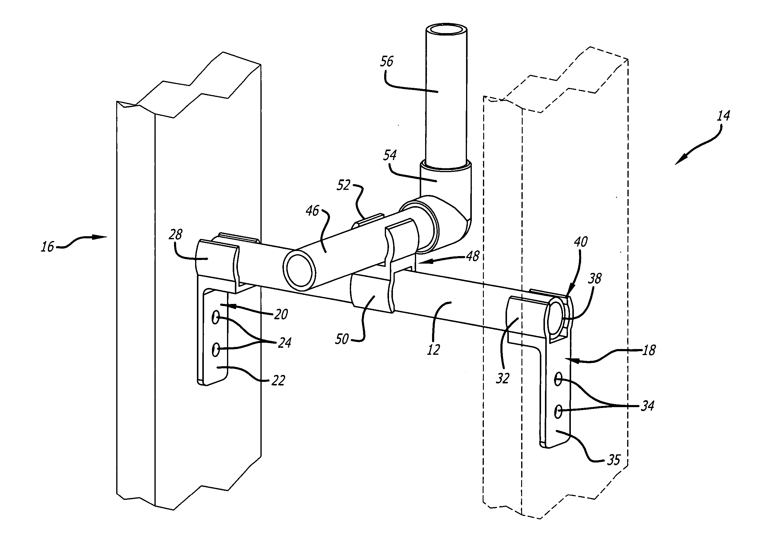
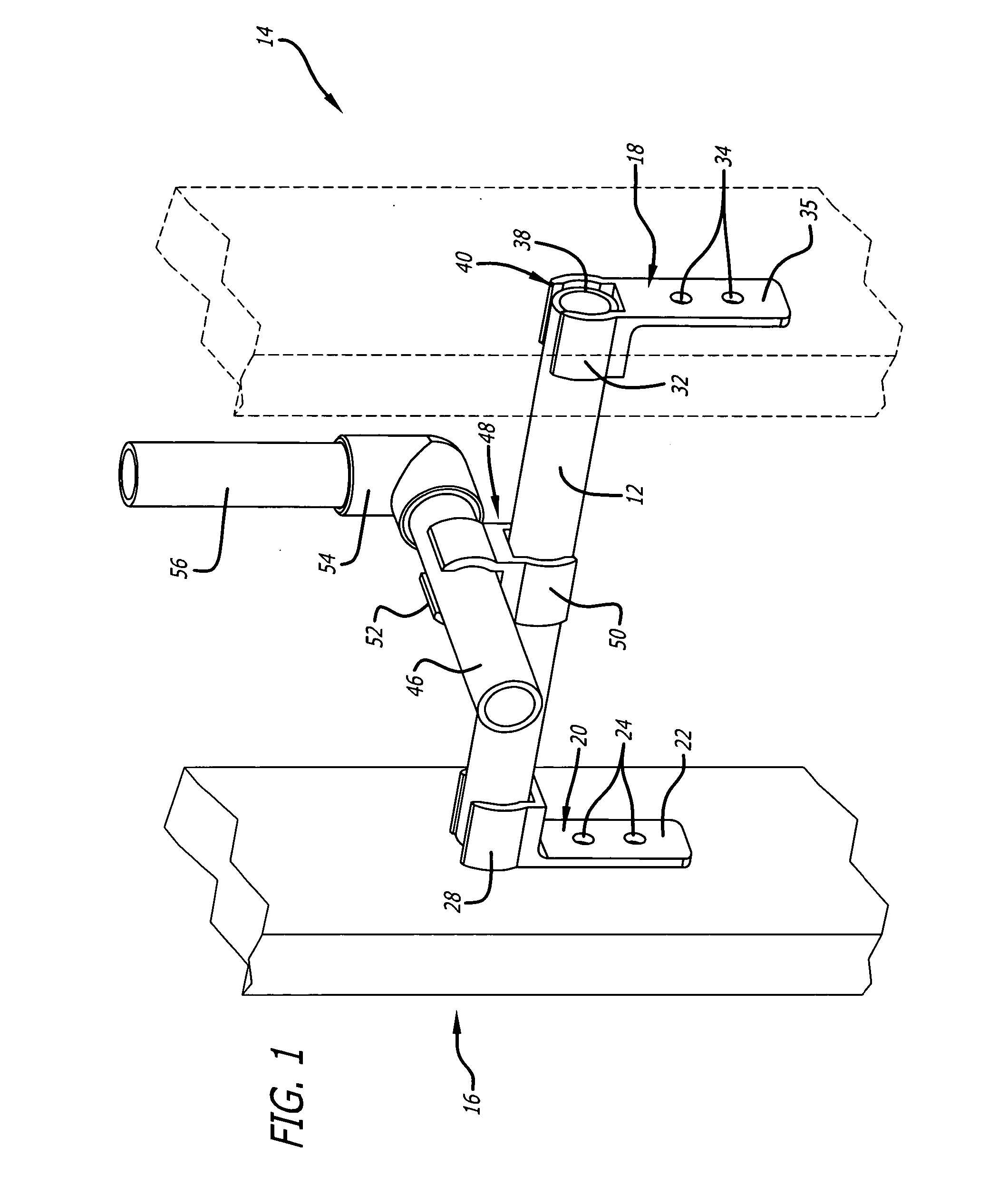
[0022] Referring more particularly to the drawings, FIG. 1 shows a support pipe 12 extending between two supports 14 and 16 which may be 2×4 inch studs within a wall. Two wall-to-pipe fittings 18 and 20 are provided, with the base portion 22 of fitting 20 being provided with holes 24 to receive nails or screws to fasten the fitting 20 to the stud 16.

[0023] At the upper end of fitting 20 is an integral, partially open snap-on clip portion 28 into which one end of the support pipe 12 may be snapped.

[0024] The other end of support pipe 12 may be snapped into the upper portion 32 of fitting 18. Openings 34 in fitting 18 serve to receive fasteners to hold the base 35 of fitting 18 to the stud 14. It may be noted that the length of support pipe 12 need not be exact, and the end 38 of support pipe 12 is shown spaced back slightly from the end 40 of circular portion 32 which faces stud 14. With the clip-on portions 28 and 32 on the fittings 18 and 20 having a substantial axial extent, the...


PUM


Abstract

A plastic pipe support assembly includes a pair of snap-on wall brackets or fittings with each bracket or fitting including a base portion and a snap-on, pipe receiving portion. The base portion includes holes for receiving nails or screws for mounting to studs in a building, for example; and the snap-on pipe receiving portion includes a pair of jaws for extending around a support pipe, with the opening between the jaws having a spacing which is less than the diameter of the support pipe so that the support pipe may be snapped into the jaws, and held firmly in place. One or more pipe-to-pipe fittings may be provided with each fitting having a pair of pipe receiving jaws, for mounting water pipes to the support pipe. The support pipe and the brackets or fittings may be all formed of the same type of plastic as the water pipe, such as polyvinyl chloride, or chlorinated polyvinyl chloride. Plastic solvent may be employed to bond the pipes and fittings together.

Description

FIELD OF THE INVENTION [0001] This invention relates to pipe supports, principally for plastic pipe. BACKGROUND OF THE INVENTION [0002] The purpose of the present invention is the support of plumbing pipes in the walls of structures. If pipes are not supported, they may shake and rattle when faucets are turned on and off and, without support, the weight of water in the pipes may cause pipes to sag and be damaged. Also, when the pipes protrude through the walls, the supports keep pipes lined up during the installation of drywall and also hold the pipes from behind, enabling the plumber to attach end valves on the outside of the wall. [0003] In accordance with prior practice various metal support straps are sold with holes along their length. These supports are nailed between wall studs, and pipes are wired or clamped to the metal straps. Some metal supports telescope to fit between studs and others are cut with a hack saw to fit between the studs. If a metal support strap is not used...

Claims


Application Information

Patent Timeline
IPC IPC(8): F16L3/08F16L3/13
CPCF16L3/13F16L3/085
Inventor KING, ROBERT W.
Owner KING ROBERT W
Learn More