
Ultrasonic welded initiator and connector socket

a technology of initiators and connector sockets, applied in the direction of electric fuzes, pedestrian/occupant safety arrangements, vehicular safety arrangements, etc., can solve the problems of increasing the cost of inflators, occupants with belts experiencing an impact on the interior of the car, etc., and achieves reliable operation and easy electrical connection of modules

Inactive Publication Date: 2005-06-09
AUTOLIV ASP INC
View PDF20 Cites 30 Cited by
  • Summary
  • Abstract
  • Description
  • Claims
  • Application Information

AI Technical Summary

Benefits of technology

[0008] The apparatus and method of the present invention have been developed in response to the present state of the art, and in particular, in response to the problems and needs in the art that have not yet been fully solved by currently available airbag inflators and related hardware and methods. Thus, it is an overall purpose of the present invention to provide an airbag inflation apparatus and method that provides for economical production and assembly of the airbag inflator, easy electrical connection of the module to the vehicle, and reliable operation after assembly.
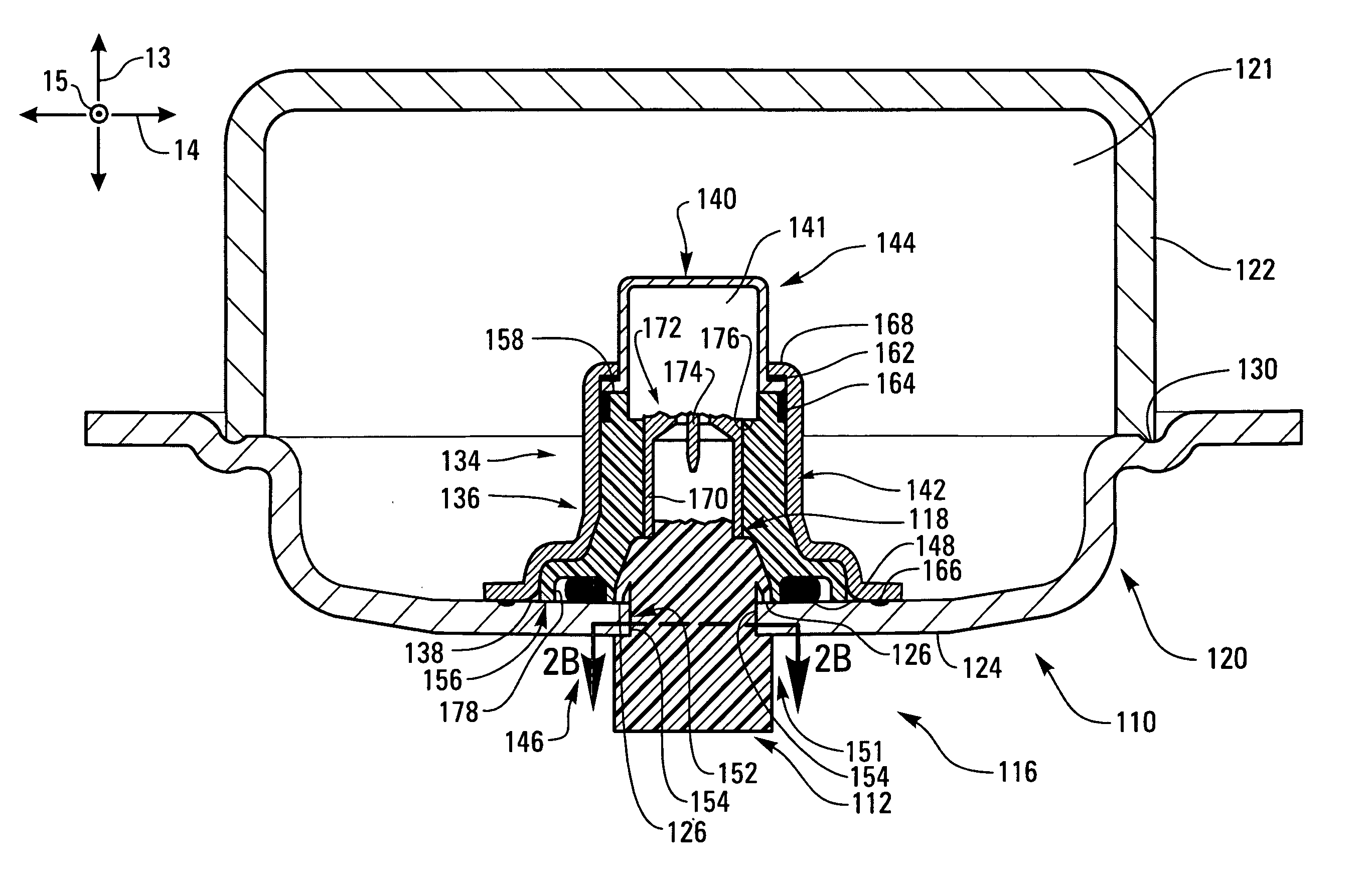
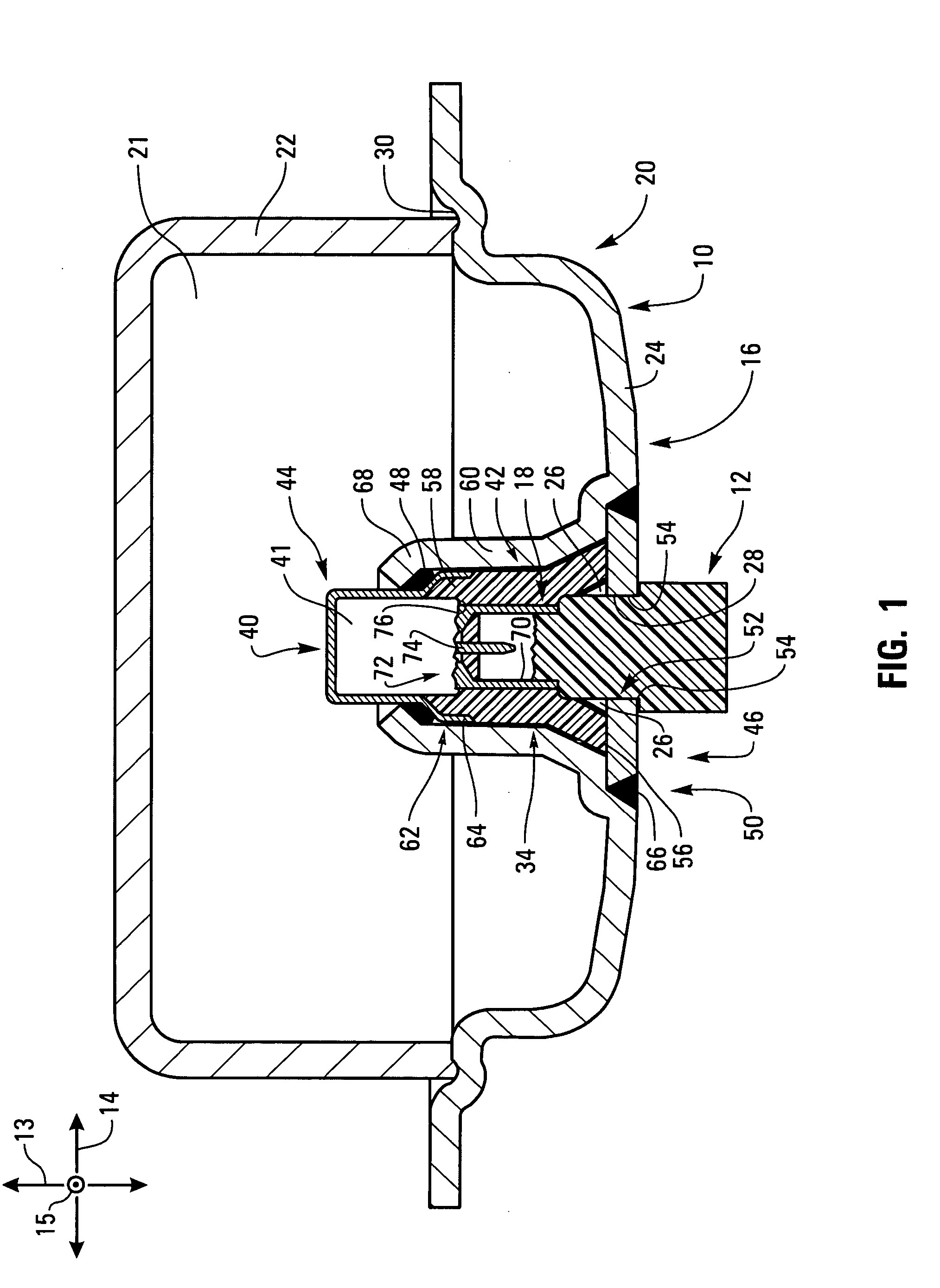
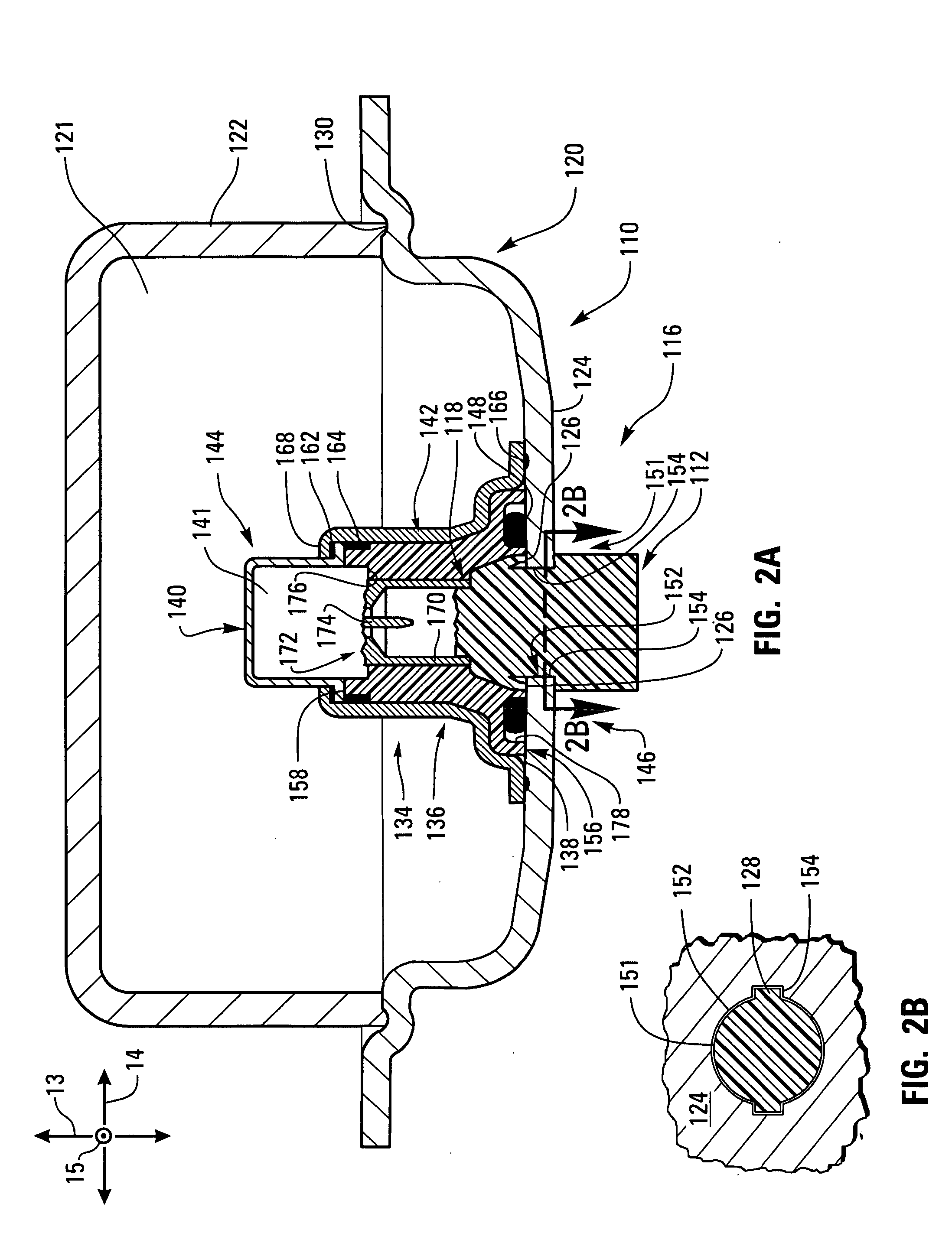
[0018] The connector may be easily coupled to the inflator. The distal ring of the skirt of the connector is inserted into the annular space between the retainer and the collar. The deflectable tabs deflect to slide past the splines of the retainer. Meanwhile, distal ring may have to be rotated slightly to cause the ribs of the distal ring mesh with the splines of the retainer. This rotation is facilitated by chamfers on the splines of the retainer and the splines of the connector.
[0019] Once the ribs and splines mesh, the skirt may be further inserted until the deflectable tabs move back to their inwardly-extending, relatively undeflected positions. In doing so, the deflectable tabs abut the inward faces of the splines to block withdrawal of the skirt from the receptacle. Thus, the connector is nonremovably retained by the retainer. The splines and ribs continue to mesh to prevent relative rotation between the connector and the inflator.
[0036] The body has an outward shoulder that abuts the interior of the collar. The collar has a generally conical interior surface that receives the outward shoulder. An annular ridge extends from the generally conical interior surface to press into the outward shoulder. Deformation of the outward shoulder by the annular ridge forms a seal tending to keep moisture out of the initiator and the remainder of the inflator. The collar is crimped to retain the body, cover, and initiator.
[0051] According to other alternative embodiments, connectors and receptacles having other features besides splines and / or ribs may be used to “key code” an inflation assembly to prevent improper assembly. For example, a connector may have a circular, triangular, square, pentagonal, or hexagonal shape. An inflator receptacle may have a corresponding shape that receives the shape of the connector. Such shapes may also enable insertion of the connector into the receptacle in multiple orientations without permitting post-assembly rotation.
[0059] Through the system and method of the present invention, an inflator may be relatively inexpensively manufactured and assembled with reduced use of time- and labor-intensive operations such as machining of socket parts. The inflator may be reliably sealed without the installation of extra sealing parts. These and other features and advantages of the present invention will become more fully apparent from the following description and appended claims, or may be learned by the practice of the invention as set forth hereinafter.

Problems solved by technology

In more severe collisions, however, even belted occupants may experience an impact with the car's interior.
The adaptors used in these currently known processes are complex parts that must be individually manufactured to accommodate the connector geometries used by various automotive manufacturers.
Often the adaptors are custom-machined parts that are costly to produce and use, thus raising the costs of inflators.

Method used


Image

  • Ultrasonic welded initiator and connector socket
  • Ultrasonic welded initiator and connector socket
  • Ultrasonic welded initiator and connector socket

Examples


Embodiment Construction

[0070] The presently preferred embodiments of the present invention will be best understood by reference to the drawings, wherein like parts are designated by like numerals throughout. It will be readily understood that the components of the present invention, as generally described and illustrated in the figures herein, could be arranged and designed in a wide variety of different configurations. Thus, the following more detailed description of the embodiments of the apparatus, system, and method of the present invention, as represented in FIGS. 1 through 7, is not intended to limit the scope of the invention, as claimed, but is merely representative of presently preferred embodiments of the invention.

[0071] The present invention utilizes a number of different principles to enhance the cost-effectiveness, electrical connectability, and reliability of inflators. Through the use of the present invention, labor intensive processes such as insert molding and machining may be reduced o...


PUM


Abstract

The present invention provides an airbag inflator assembled, in part, using ultrasonic welding. The inflator includes a housing adapted to receive an initiator assembly and an adaptor socket to connect the inflator to the electronic systems of the vehicle. The initiator and the adaptor socket are welded together at a point of interface through the housing of the inflator using an ultrasound welding process. Joint seals are provided that allow the production of a gas-tight seal upon completion of assembly of the airbag inflator.

Description

CROSS-REFERENCED RELATED APPLICATIONS [0001] This application is a continuation-in-part of prior application Ser. No. 10 / 614,155, filed Jul. 7, 2003, entitled “Airbag Initiator Cover Attachment Apparatus and Method,” which is incorporated herein in its entirety by this reference.BACKGROUND OF THE INVENTION [0002] Safety belts are designed to protect the occupants of a vehicle during events such as automobile collisions. In low-speed collisions, the occupants are generally protected from impact with objects located inside the vehicle such as the windshield, the instrument panel, a door, the side windows, or the steering wheel by the action of the safety belt. In more severe collisions, however, even belted occupants may experience an impact with the car's interior. Airbag systems were developed to supplement conventional safety belts by deploying into the space between an occupant and an interior object or surface in the vehicle during a collision event. The airbag acts to decelerate...

Claims


Application Information

Patent Timeline
Patent Type & Authority Applications(United States)
IPC IPC(8): B60R21/26B60R21/264
CPCB60R21/26B60R2021/26076B60R2021/26029B60R21/2644
Inventor BRISIGHELLA, DARIO G. JR.SMITH, BRADLEY W.ELLIS, KELLYRASMUSSEN, KIRKCOX, MATT
Owner AUTOLIV ASP INC
Learn More