Electro-optic displays

Inactive Publication Date: 2005-06-09
E INK CORPORATION
View PDF1 Cites 262 Cited by
  • Summary
  • Abstract
  • Description
  • Claims
  • Application Information

AI Technical Summary

Benefits of technology

[0040] This invention also provides an electro-optic display comprising: a backplane comprising at least one electrode; a layer of electro-optic material; and a lamination adhesive disposed between

Problems solved by technology

Nevertheless, problems with the long-term image quality of these displays have prevented their widespread usage.
For example, particles that make up electrophoretic displays tend to settle, resulting in inadequate service-life for these displays.
If the resistivity of the adhesive layer is too high, a substantial voltage drop will occur within the adhesive layer, requiring an increase in voltage across the electrodes.
Increasing the voltage across the electrodes in this manner is undesirable, since it increases the power consumption of the display, and may require the use of more complex and expensive control circuitry to handle the increased voltage involved.
It is also ne

Method used


Image

  • Electro-optic displays
  • Electro-optic displays
  • Electro-optic displays

Examples


example 1

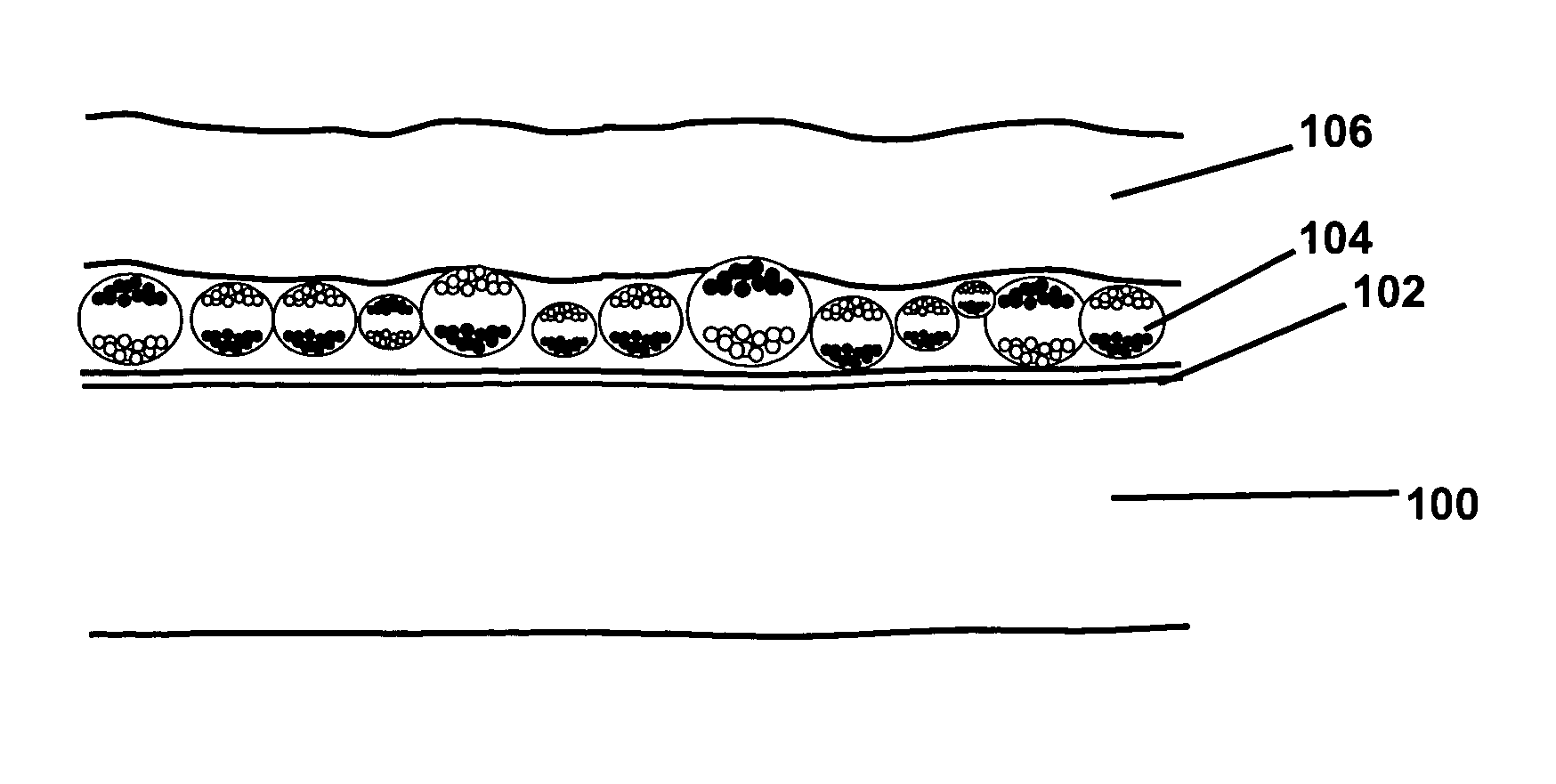
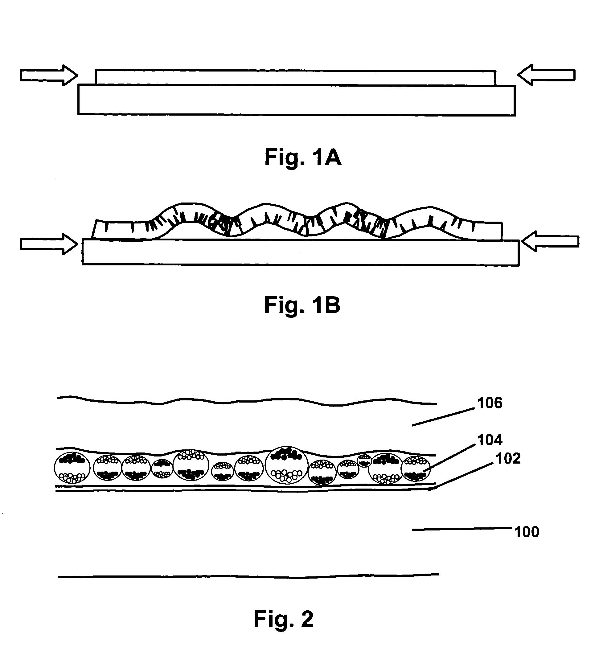
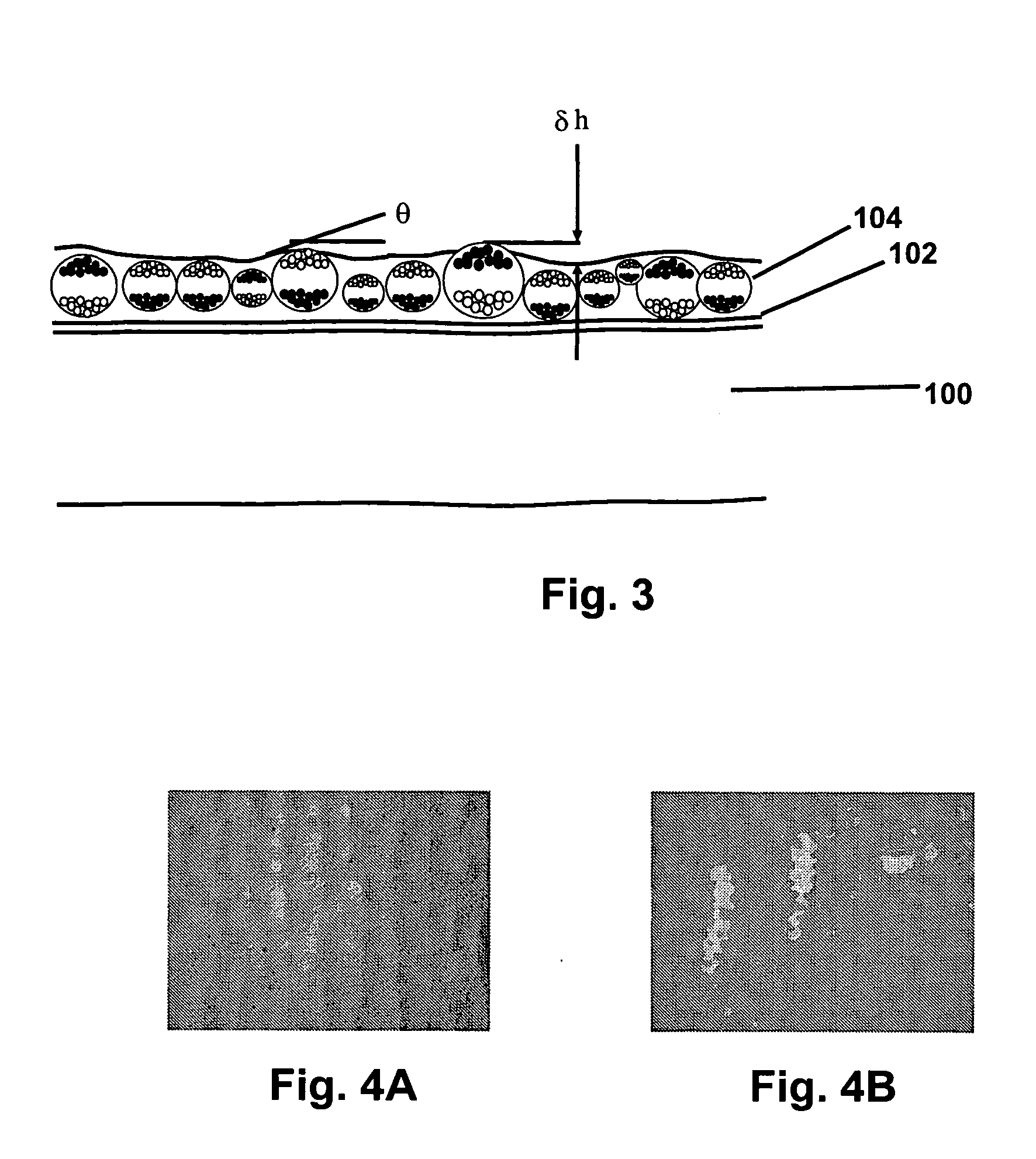
[0067] An internal phase was prepared comprising polymer-coated titania white particles and polymer-coated carbon black particles in a hydrocarbon suspending fluid. This internal phase was encapsulated in gelatin / acacia microcapsules substantially as described in Paragraphs [0069] to [0074] of the aforementioned 2002 / 0180687. The resultant microcapsules were separated by size and capsules having an average particle size of about 35 μm were used in the following experiments. The microcapsules were mixed into a slurry with a polyurethane binder and coated by a roll-to-roll process at a dry coating weight of 18 g m−2 on to the surface of a 7 mil (177 μm) poly(ethylene terephthalate) film carrying an indium tin oxide (ITO) layer on one surface, the microcapsules being deposited on the ITO-covered surface, substantially as described in Paragraphs [0075] and [0076] of the aforementioned 2002 / 0180687. The capsule-bearing film was then formed into a front plane laminate by laminating it to ...


PUM


Abstract

An electro-optic display comprises first and second substrates and a lamination adhesive layer and a layer of an electro-optic material disposed between the first and second substrates, the lamination adhesive layer having a thickness of from about 14 to about 25 μm.

Description

REFERENCE TO RELATED APPLICATIONS [0001] This application claims benefit of Provisional Applications Serial No. 60 / 481,133, filed Jul. 24, 2003 and Serial No. 60 / 481,320, filed Sep. 2, 2003. [0002] This application is also related to application Ser. No. 10 / 064,389, filed Jul. 2, 2002 (Publication No. 2003 / 0025855), which itself claims priority of Provisional Application Serial No. 60 / 304,117, filed Jul. 9, 2001.[0003] The entire contents of these copending applications, and of all other U.S. patents and published and copending applications mentioned below, are herein incorporated by reference. BACKGROUND OF INVENTION [0004] This invention relates to improvements in electro-optic displays. More specifically, in one aspect this invention relates to electro-optic media and displays in which the thickness of a lamination adhesive layer is controlled to avoid certain problems otherwise experienced in such displays. In another aspect, this invention relates to the prevention of void grow...

Claims


Application Information

Patent Timeline
IPC IPC(8): G02B26/00G02FG02F1/167
CPCG02B26/02G02F2202/28G02F1/167
Inventor HONEYMAN, CHARLES H.DOSHI, HARITSOHN, SEUNGMANCHEN, EVALECAIN, RICHARD D.PANG, SIMONDUTHALER, GREGG M.
Owner E INK CORPORATION
Why Eureka
Try Eureka