Tracking servo control apparatus and method using rotatable grating

a servo control and rotatable technology, applied in the direction of data recording, instruments, disposition/mounting of heads, etc., can solve the problems of limited dpp method application to both media having different track pitches, limitation in reducing track pitch, and inability to accurately track servo control operation.

Inactive Publication Date: 2005-06-09
SAMSUNG ELECTRO MECHANICS CO LTD
View PDF1 Cites 12 Cited by
  • Summary
  • Abstract
  • Description
  • Claims
  • Application Information

AI Technical Summary

Benefits of technology

[0036] Another object of the invention is to provide a tracking servo control apparatus and method capable of compensating for misalignment of an image focused on a photodetector thereof due to rotation of a grating thereof, thereby achieving an accurate tracking servo control operation based on a DPP method.

Problems solved by technology

However, the maximum recording capacity of high density DVDs, which are currently available, is only about 4.7 GB.
However, there may be a limitation in reducing the track pitch because crosstalk may be generated during playback of the disc due to such a reduction in track pitch.
That is, where the track pitch is too narrow, there may be a problem in that, when information recorded on one track is reproduced, information recorded on a track adjacent to the currently reproduced track may be included in a signal, which is currently reproduced.
However, it is difficult for the DPP method to be applied to both the media having different track pitches because the DPP method requires an accuracy in positioning side beams on opposite track edges.
Furthermore, there may be a drawback in that a considerable reduction in detected tracking error values occurs when the DPP method is applied to discs having different track pitches.
In this case, it may be impossible to achieve a desired servo control operation.
In other words, it is difficult for the DPP method to be applied to both the DVD-ROM and the DVD-RAM because the DVD-ROM has a track pitch of 0.74 μm, whereas the DVD-RAM has a track pitch of 0.615 μm.

Method used


Image

  • Tracking servo control apparatus and method using rotatable grating
  • Tracking servo control apparatus and method using rotatable grating
  • Tracking servo control apparatus and method using rotatable grating

Examples


Embodiment Construction

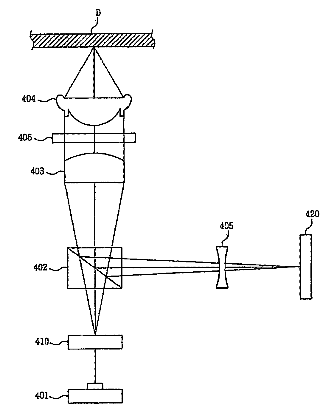
[0063] Now, a preferred embodiment of the present invention will be described with reference to FIG. 4.

[0064]FIG. 4 is a schematic view illustrating the configuration of a DVD-ROM optical system enabling data reproduction of a DVD-RAM in accordance with the present invention. FIG. 5 is a schematic view illustrating the configuration of an 8-section photodetector included in the DVD-ROM optical system which enables data reproduction of a DVD-RAM in accordance with the present invention.

[0065] Referring to FIG. 4, the DVD-ROM optical system includes a light source 401 adapted to emit a divergent laser beam having a wavelength of 650 nm, and a beam splitter 402 adapted to transmit the divergent laser beam emitted from the light source 401 while reflecting a laser beam reflected from the recording surface of an optical disc D.

[0066] The divergent laser beam transmitted through the beam splitter 402 is irradiated onto a collimating lens 403 which, in turn, converts the laser beam into...


PUM

PropertyMeasurementUnit
wavelengthaaaaaaaaaa
distanceaaaaaaaaaa
angleaaaaaaaaaa

Abstract

A tracking servo control apparatus and method in which the distance between a main beam and a side beam is adjustable by a rotatable grating, so as to perform a tracking servo control operation in accordance with a differential push-pull (DPP) method for both the DVD-ROM (Read Only Memory) and the DVD-RAM (Random Access Memory) having different track pitches.

Description

BACKGROUND OF THE INVENTION [0001] 1. Field of the Invention [0002] The present invention relates to a tracking servo control apparatus and method using a rotatable grating, and more particularly to a tracking servo control apparatus and method capable of compensating for an offset, which is involved in push-pull signals generated in accordance with detection of side beams, due to rotation of a grating, during a tracking servo control operation using a differential push-pull (DPP) method. [0003] 2. Description of the Related Art [0004] In pace with recently increased use of large-capacity data, development of optical discs which use a particular optical system to achieve recording of data thereon and reproduction of data recorded thereon has been increased. Specifically, in such a optical disc, recording of data is carried out by varying the transmittance, reflectance, phase, and polarity of light to be irradiated onto a data area of the optical disc in accordance with the data, whe...

Claims


Application Information

Patent Timeline
Patent Type & Authority Applications(United States)
IPC IPC(8): G11B7/09G11B7/00G11B7/135G11B7/1353
CPCG11B7/0903G11B2007/0006G11B7/1353
Inventor SHIN, DONG-IKHWANG, WON-JAEKYONG, CHON-SUPARK, SUNG-KYUNLEE, HO-CHEOLJEONG, HO-SEOP
Owner SAMSUNG ELECTRO MECHANICS CO LTD
Why Eureka
Try Eureka