
Diffractive optical element, objective optical system, optical pick-up device and optical information recording reproducing apparatus

a technology of optical elements and optical pickup devices, applied in the field of optical pickup devices and optical information recording reproducing apparatus, can solve the problems of increasing the production cost of laser light sources, increasing the production cost of optical pick-up devices, and unable to obtain stable recording/reproducing characteristics of high density optical disks. achieve the effect of reducing production costs and increasing yield

Inactive Publication Date: 2005-06-09
KONICA MINOLTA OPTO
View PDF1 Cites 14 Cited by
  • Summary
  • Abstract
  • Description
  • Claims
  • Application Information

AI Technical Summary

Benefits of technology

[0011] Then, in the diffractive optical element according to the present invention, a second diffractive structure in which a ratio δφB12 of the optical path length of the wavelength λ1 and wavelength λ2 is different from the ratio δφA12 of the optical path length in the above first diffractive structure, is provided. By using the difference between the diffraction actions of the first diffractive structure and the second diffractive structure, the wavelength dependency of the spherical aberration of the first diffractive structure in the blue violet wavelength range can be controlled, or suppressed small. Hereby, an increase of a yield in the mass production of the blue violet laser light source, and a reduction of the production cost of the blue violet laser light source or optical pick-up device become possible. Further, even when the temperature is changed, a stable recording / reproducing of the information on the high density optical disk can also be conducted.

Problems solved by technology

However, in the diffractive sructure which generates the diffraction light of the combination of the diffraction order n1 and the diffraction order n2, because a changing amount of the spherical aberration per unit wavelength becomes large, the selection of the laser light source becomes necessary, and there are a problem which results in, an increase of the production cost of the laser light source, and an increase of the production cost of the optical pick-up device, and a problem that, because the spherical aberration of the objective optical system largely changes by the wavelength change of the laser light source following the temperature change, the stable recording / reproducing characteristic for the high density optical disk can not be obtained.

Method used


Image

  • Diffractive optical element, objective optical system, optical pick-up device and optical information recording reproducing apparatus
  • Diffractive optical element, objective optical system, optical pick-up device and optical information recording reproducing apparatus
  • Diffractive optical element, objective optical system, optical pick-up device and optical information recording reproducing apparatus

Examples


first embodiment

The First Embodiment

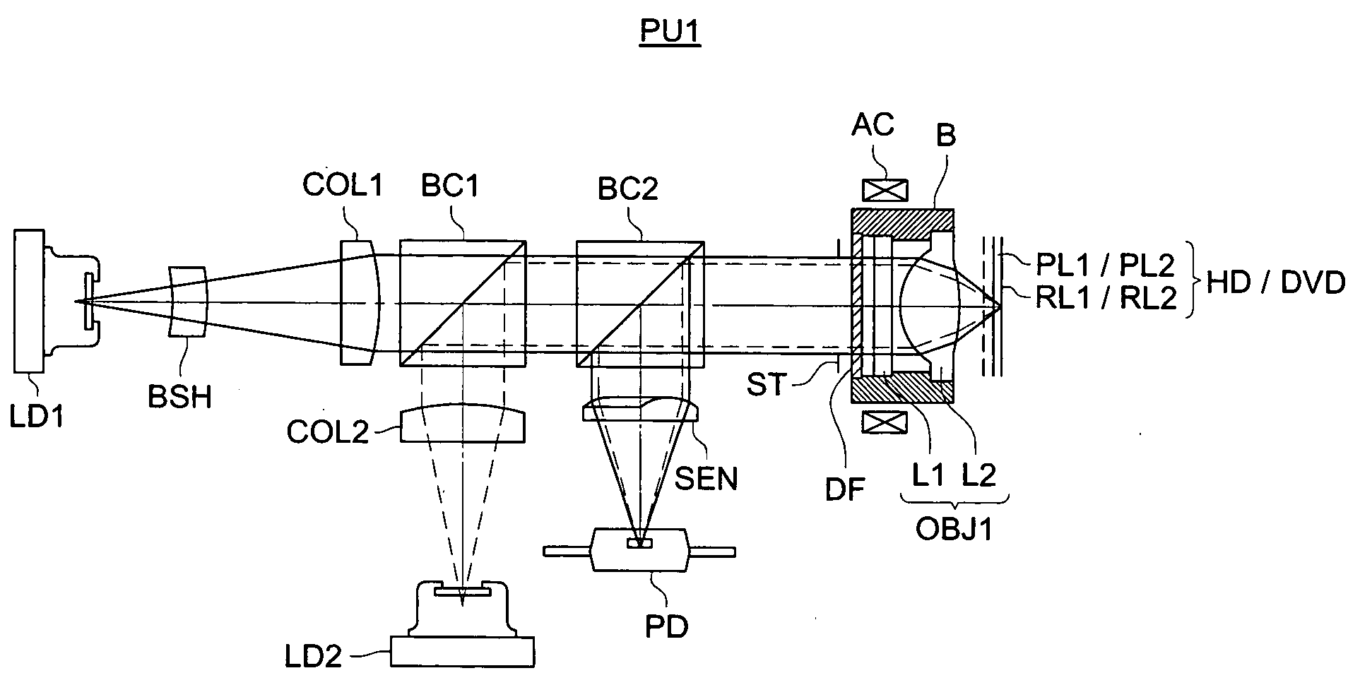
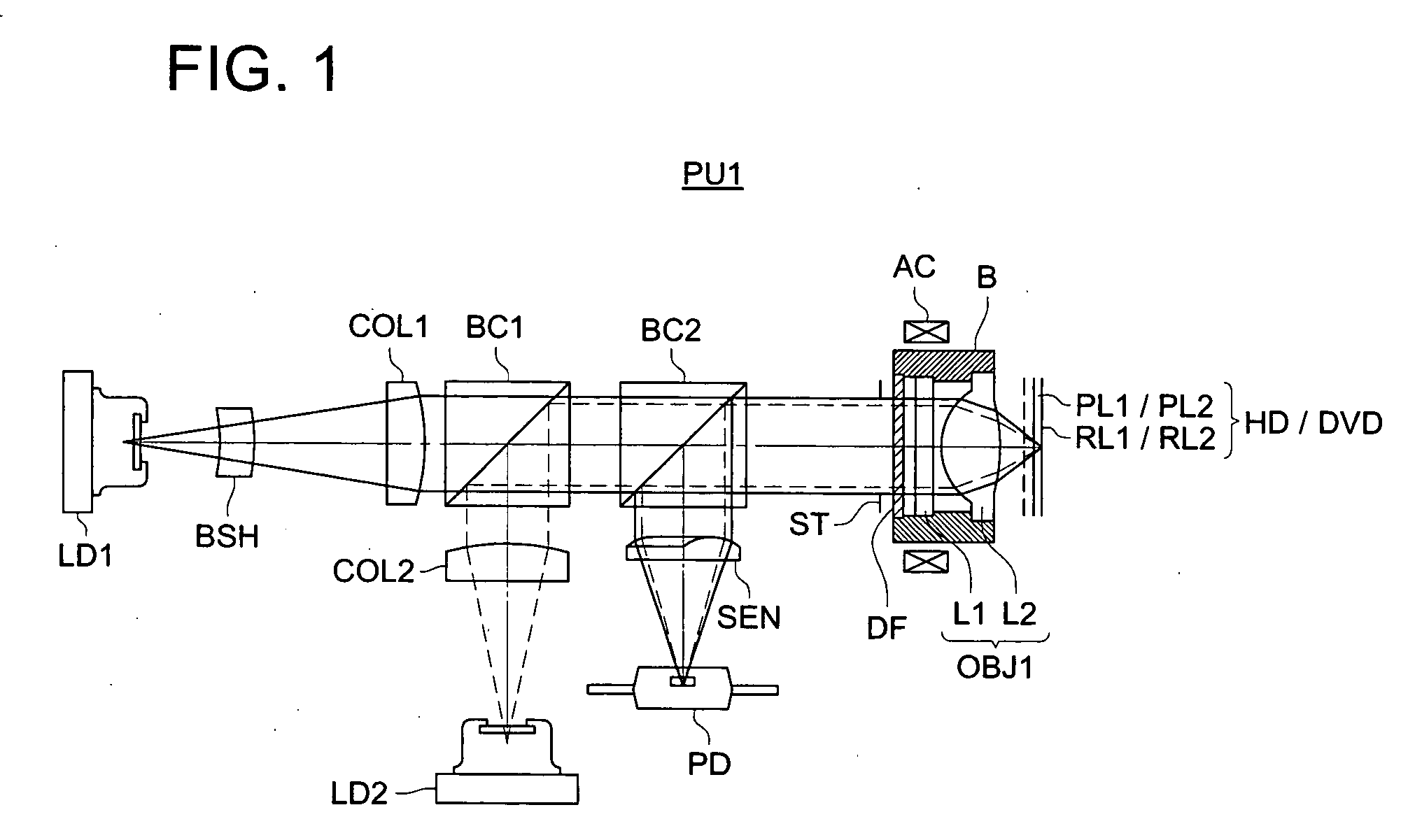
[0085]FIG. 1 is a view generally showing the structure of the first optical pick-up device PU1 by which the recording / reproducing of the information can be adequately conducted on the high density optical disk HD (the first optical disk) and DVD (the second optical disk). The optical specification of the high density optical disk HD is wavelength λ1=405 nm, the thickness t1 of the protective layer PL1=0.1 mm, numerical aperture NA1=0.85, and the optical specification of DVD is wavelength λ2=655 nm, the thickness t2 of the protective layer PL2=0.6 mm, numerical aperture NA2=0.65. However, a combination of the wavelength, thickness of the protective layer, and numerical aperture is not limited to this.

[0086] As shown in FIG. 1, the optical pick-up device PU1 is composed of the blue violet semiconductor laser LD1 projecting the first light flux, the red semiconductor laser LD2 projecting the second light flux, a photo-detector-PD commonly used for the high density ...

second embodiment

The Second Embodiment

[0096] Next, the second embodiment of the present invention will be described, however, the same sign is given to the same structure as the first embodiment, and the explanation will be omitted.

[0097]FIG. 3 is a view generally showing the structure of the second optical pick-up device PU2 by which the recording / reproducing of the information can be adequately conducted on the high density optical disk HD (the first disk), DVD (the second disk) and CD (the third optical disk). The optical specification of the high density optical disk HD is wavelength λ1=405 nm, the thickness t1 of the protective layer PL1=0.1 mm, numerical aperture NA1=0.85, the optical specification of DVD is wavelength λ2=655 nm, the thickness t2 of the protective layer PL2=0.6 mm, numerical aperture NA2=0.65, and the optical specification of CD is wavelength λ3=785 nm, the thickness t3 of the protective layer PL3=1.2 mm, numerical aperture NA3=0.45.

[0098] However, a combination of the wavel...

example 1

[0113] The present Example is an optical element appropriate as the first objective optical system OBJ1 in the above optical pick-up device PU1, the lens data is shown in Table 1, and the optical path view is shown in FIG. 4. The optical element of the present Example is structured by the spherical aberration correction element L1 which is a plastic lens, in which the first diffractive structure DOE1 is formed on the optical surface S1 of the laser light source side, and the second diffractive structure DOE2 is formed on the optical surface S2 of the optical disk side, and the light converging element L2 which is a glass lens both surfaces of which are aspheric surfaces. Hereupon, hereinafter (including the lens data in Table), exponential of 10 (for example, 2.5×10⁻³) is expressed by using E (for example, 2.5E-3). Further, the following signs express that, r (mm) is a paraxial radius of curvature, d1 (mm) is an interval on optical axis when the high density optical disk HD is used,...


PUM

PropertyMeasurementUnit
wavelengthaaaaaaaaaa

Abstract

A diffractive optical element, comprises a first diffractive structure to generate n11-th order diffracted ray when a first light flux having λ1 (nm) of a wavelength comes in and to generate n21-th order diffracted ray (n11.≧n21) when a second light flux having λ2 (nm) (λ2>λ1) comes in; and a second diffractive structure to generate n12-th order diffracted ray when the first light flux comes in and to generate n22-th order diffracted ray (n12.≧n22) when the second light comes in. The diffractive optical element satisfies the following formula: δφA12≠δφB12, where δφA12={n11·λ1 / (N11−1)} / {n21·λ2 / (N21−1)}, and δφB12={n12·λ1 / (N12−1)} / {n22·λ2 / (N22−1)}, wherein N11, N21 are refractive index of the first diffractive structure respectively for λ1 and λ2, and N12, N22 are refractive index of the second diffractive structure respectively for λ1 and λ2.

Description

BACKGROUND OF THE INVENTION [0001] The present invention relates to a diffractive optical element, objective optical system, optical pick-up device and optical information recording reproducing apparatus, and particularly, to an optical pick-up device and optical information recording reproducing apparatus by which, by using light fluxes projected from light sources of different wavelengths, the information can be recorded and / or reproduced for optical information recording media, and to a diffractive optical element and objective optical system appropriate when used for them. [0002] Conventionally, an optical pick-up device which can record / reproduce for a plurality of kinds of optical disks having different recording densities, is well-known. For example, there is a device by which a DVD (Digital Versatile Dik) and a CD (Compact Disk) are recorded / reproduced by using an optical pick-up device. Further, recently, as an optical disk having different recording densities, an optical p...

Claims


Application Information

Patent Timeline
Patent Type & Authority Applications(United States)
IPC IPC(8): G02B5/18G02B13/00G02B13/18G02B27/42G11B7/00G11B7/1353G11B7/1369G11B7/139G11B7/1392
CPCG11B7/1353G11B7/1369G11B2007/0006G11B7/13922G11B7/139G02B13/001G02B27/42G11B7/1374G02B5/18G02B13/00
Inventor KIMURA, TOHRU
Owner KONICA MINOLTA OPTO
Features
  • Generate Ideas
  • Intellectual Property
  • Life Sciences
  • Materials
  • Tech Scout
  • Unparalleled Data Quality
  • Higher Quality Content
  • 60% Fewer Hallucinations
Learn More