
Apparatus for producing scored lines in a film

Inactive Publication Date: 2005-06-09
MARS INC
View PDF9 Cites 16 Cited by
  • Summary
  • Abstract
  • Description
  • Claims
  • Application Information

AI Technical Summary

Benefits of technology

[0035] Alternatively, the projection causes the formation of a bead on the surface of the said plastic layer along each side of the scored line, one of the said beads providing a higher mechanical resistance to the said plastic layer with respect to the other of the said beads.
[0083] When opening the packaging according to the invention, the tear is propagated along the scored line thus produced. A directed and clean opening of the packaging is thus provided.

Problems solved by technology

These packages, which are already known, have certain drawbacks, especially connected with their method of opening.
This is because resorting to a cutting tool such as a pair of scissors or knife lacks practicality, it being possible, for example, for this tool to be soiled by the product contained inside the packaging.
Thus, either partial opening of the packaging or a tear below the level of the product contained in the packaging is then obtained, which causes an undesired spill of this product.
However, the main drawback of this scoring carried out by applying a laser beam to the outer face of the packaging walls is that of impairing the external appearance of the packaging once said scoring has been carried out.
Although the technology proposed by this document is satisfactory, nevertheless it is dependent on the presence of the metal film.
More generally, technologies using lasers have a high investment cost, and also a high operational cost associated with the maintenance of the laser tools and the limited production rate of these technologies.
Furthermore, their implementation in the absence of a metal interlayer is very awkward.

Method used


Image

  • Apparatus for producing scored lines in a film
  • Apparatus for producing scored lines in a film
  • Apparatus for producing scored lines in a film

Examples


Embodiment Construction

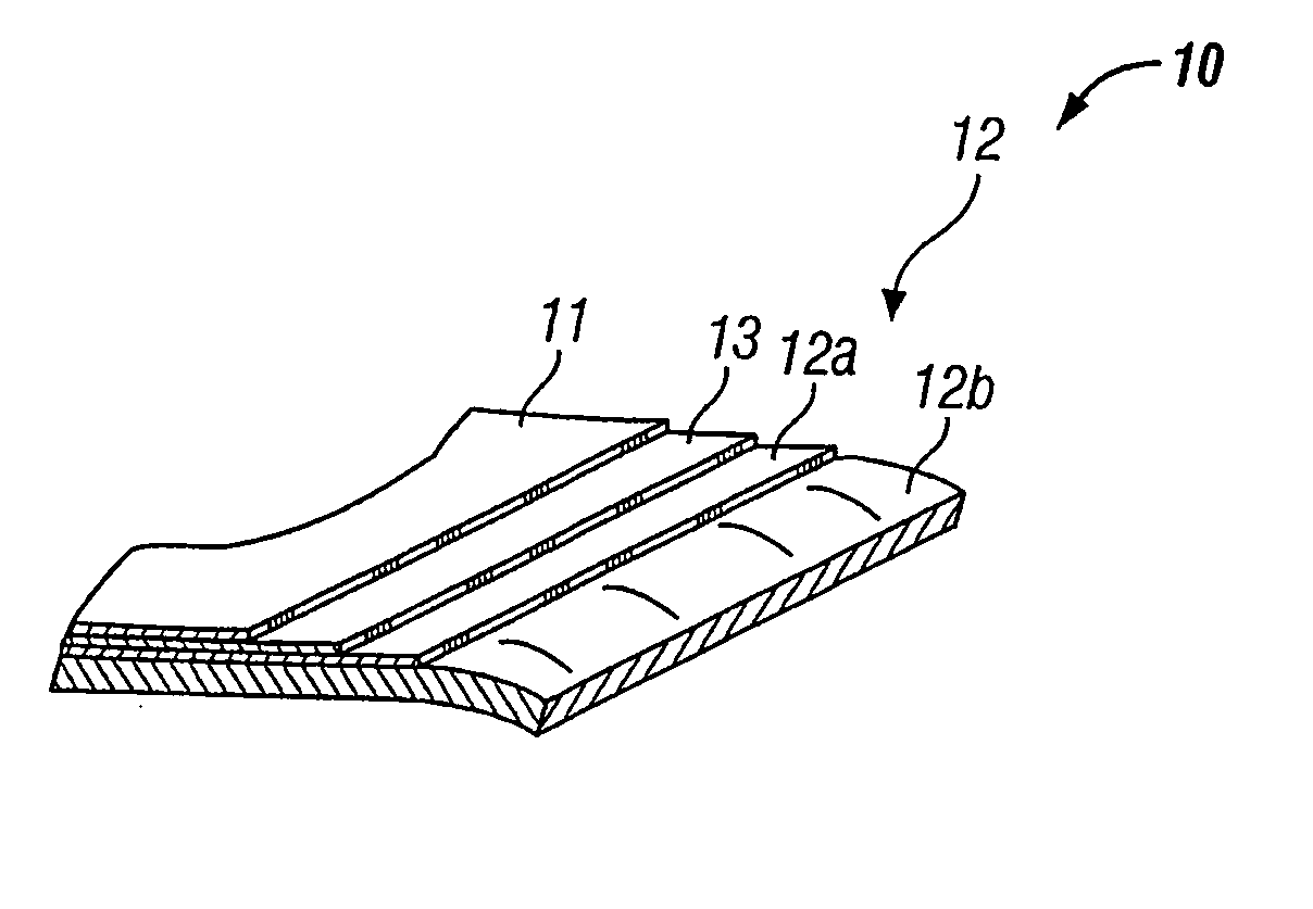
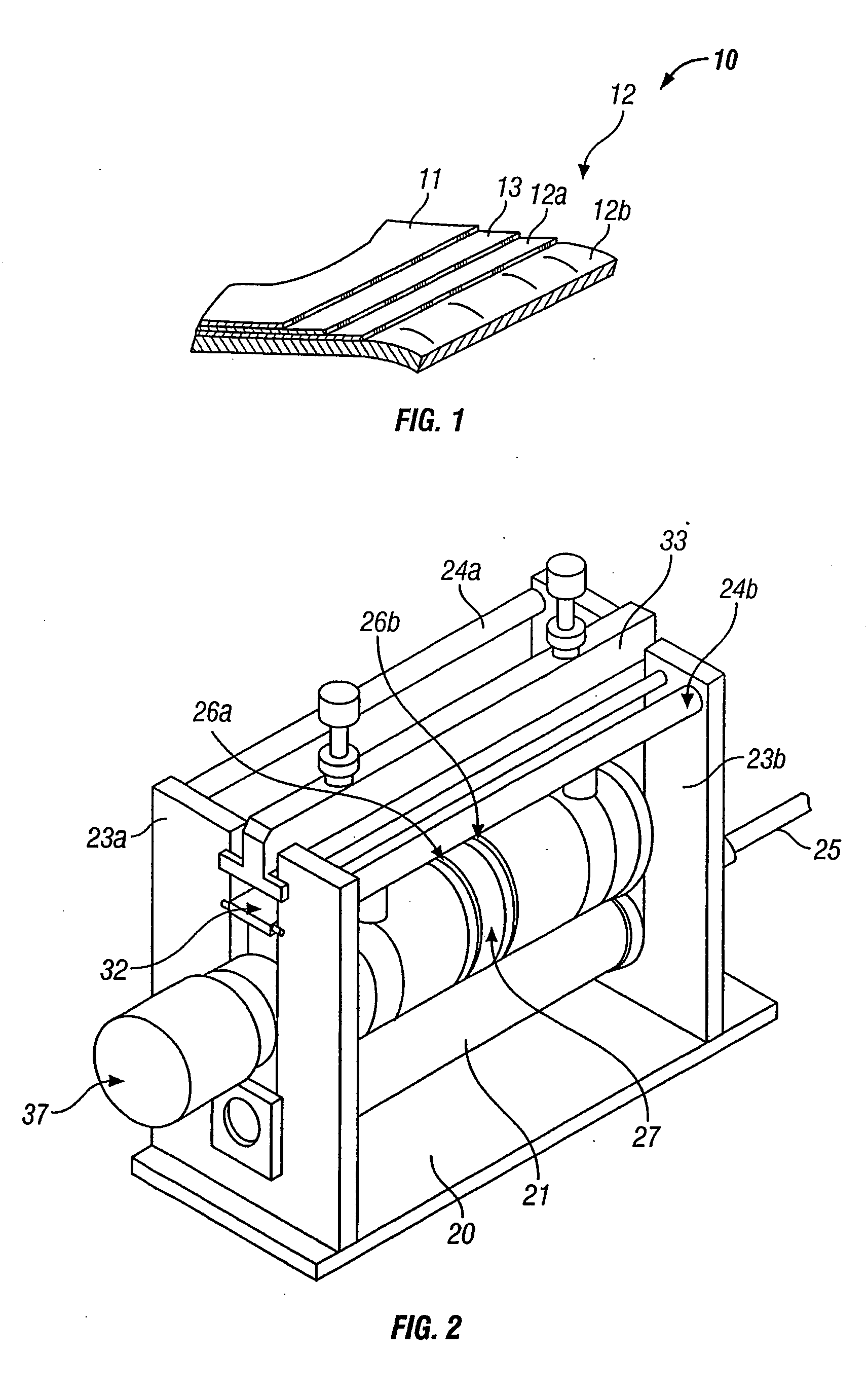
[0118]FIG. 1 illustrates a film structure typically used for manufacturing packages, especially in the form of pouches, intended to contain foodstuffs especially for animals. For this reason, they must conventionally withstand sterilization in a moist atmosphere and under pressure.

[0119] As can be seen in this figure, this film 10 comprises three layers 11, 12, 13, that is an upper layer 11 and a lower layer 12 made of plastic and a central layer 13 made of a light metal sandwiched between the said upper 11 and lower 12 layers. The upper layer 11 forms the outer face of the packages, while the lower layer 12 forms their inner face.

[0120] The lower layer 12 may in fact comprise one or more successive layers of plastics which may differ from each other, each one being able to fulfill a specific function. The same applies for the upper layer 11.

[0121] In the example illustrated in FIG. 1, the upper layer 11 forming the outer face of the packaging is made of polyethylene terephthalat...


PUM

PropertyMeasurementUnit
Lengthaaaaaaaaaa
Fractionaaaaaaaaaa
Fractionaaaaaaaaaa

Abstract

The present invention makes it possible to produce at least one scored line in at least one plastic outer layer of a film. The device of the invention includes bearing surface for the film and at least one projection for forming the scored line by penetration of the projection into the plastic layer when the film is in position against the said bearing surface. The projections may be arranged in the form of ribs on one or more coaxial rollers. The projections may form the scored line by ultrasonic plastic flow, the film being compressed between a sonotrode and the rollers. The invention provides methods using these devices and it also provides films having scored lines, and packages having scored lines.

Description

CROSS-REFERENCE TO RELATED APPLICATIONS [0001] This Application is a Continuation-in-part of application Ser. No. 10 / 342,603 filed on Jan. 15, 2003, and also claiming priority to PCT / 2003 / 006492 filed Jun. 19, 2003 claiming priority to EP 02291535.9 filed Jun. 19, 2002.TECHNICAL FIELD [0002] The present invention relates to a device for producing at least one scored line in at least one plastic outer layer of a film. The invention also relates to a method for producing at least one scored line in just a first plastic layer of a film comprising at least a second layer. The invention also relates to a method of manufacturing a packaging. The invention also relates to a film and a packaging having a scored line. BACKGROUND OF THE INVENTION [0003] The invention has a particularly advantageous application in the production of pouches or bags containing foodstuffs, especially animal foodstuffs, such pouches or bags being designed to be hermetically sealed by welding and heat-treated after...

Claims


Application Information

Patent Timeline
IPC IPC(8): B26D3/08B26D7/08B29C59/00B31B50/25B65D75/00B65D75/20B65D75/30B65D75/58B65D75/62
CPCB31B1/25Y10T428/24479B65D75/008B65D75/20B65D75/30B65D75/5805B26D3/085B26D7/086B29C59/007B29C2043/3636B29C2791/008B29L2009/00B29C66/9517B29C66/91651B29C66/91212B29C66/91231B29C66/91421B29C66/91431B29C66/9513B31F1/10B31B2201/257B29C65/08B29C65/086B29C65/18B29C65/7435B29C65/7437B29C66/21B29C66/232B29C66/81417B29C66/81427B29C66/81431B29C66/81433B29C66/83411B29C66/83413B29C66/83417B31B2201/255B29C66/1122B29C66/133B29C66/43B29C66/4312B29C66/432B29C66/4322B29C66/45B29C66/71B29C66/72321B29C66/72341B29C66/73921B29C66/81419B29C66/8223B29C66/9221B31B50/254B31B50/256B29K2077/00B29K2067/003B29K2023/12
Inventor BLANCHARD, DANIEL
Owner MARS INC
Learn More