System for housing/processing carrier and method for housing/processing carrier

a technology for processing carriers and carriers, applied in the field of carrier housing/processing equipment, can solve the problems of user over-burden, complicated and time-consuming processes, and complex and time-consuming processes, and achieve the effect of preventing cross-contamination in time and reliably

Inactive Publication Date: 2005-06-09
PRECISION SYST SCI
View PDF11 Cites 14 Cited by
  • Summary
  • Abstract
  • Description
  • Claims
  • Application Information

AI Technical Summary

Benefits of technology

[0058] According to this aspect of the invention, since the carrier is accommodated in the carrier housing section so as to be able to be taken out, then by exchanging the carrier or the like, it becomes possible to reliably prevent cross-contamination, to preserve the carrier, and to perform further processes.

Problems solved by technology

In order to perform these processes, there is a problem in that the carrier itself must be separated and transferred, causing concern of complicated and time-consuming processes.
In particular, in the case where these carriers themselves are transferred by hand, there is concern in that the user is over burdened and cross-contamination may be caused.
Furthermore, in the case where a non magnetic carrier is separated, it is necessary to perform the separation depending on the size and the density of the carrier, causing a problem of complicated and time-consuming processes.
Therefore, in order to perform the processes, it is necessary to complicatedly combine the drawing / discharging control, the attraction control by the magnetic field, and the transfer control of the pipette tip.
Moreover in the case where the carrier is a non magnetic carrier, there is a problem in that the separation can not be performed by the apparatus.

Method used


Image

  • System for housing/processing carrier and method for housing/processing carrier
  • System for housing/processing carrier and method for housing/processing carrier
  • System for housing/processing carrier and method for housing/processing carrier

Examples


first embodiment

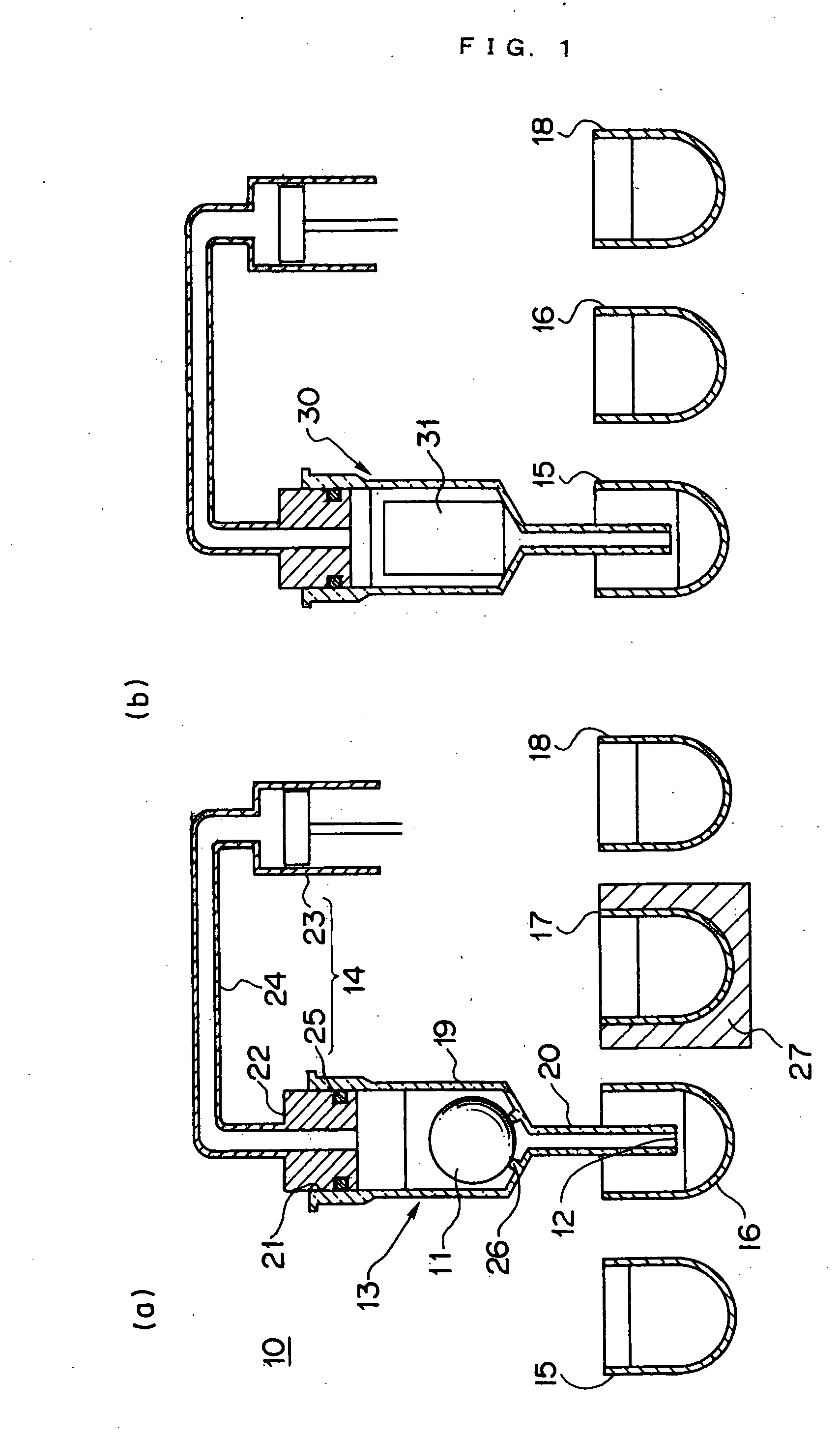
[0063] Next is a description of, a carrier housing / processing apparatus 10 according to the present invention, based on FIG. 1. The description of the respective embodiments should not be considered as limiting the present invention, unless particularly specified.

[0064] As shown in FIG. 1(a), the carrier housing / processing apparatus 10 according to the present embodiment has one spherical carrier 11 capable fixing DNA having a predetermined base sequence as a ligand on the surface, and a fluid inlet / outlet 12 for, and is provided with an approximate cylindrical carrier housing section 13 accommodating the spherical carrier 11, a drawing / discharging section 14 which draws and discharges a fluid with respect to the carrier housing section 13 through the inlet / outlet 12, and a transferring section (not shown) which relatively transfers the fluid inlet / outlet 12 of the carrier housing section 13, with respect to containers 15 to 18 externally provided.

[0065] Moreover, the carrier housi...

second embodiment

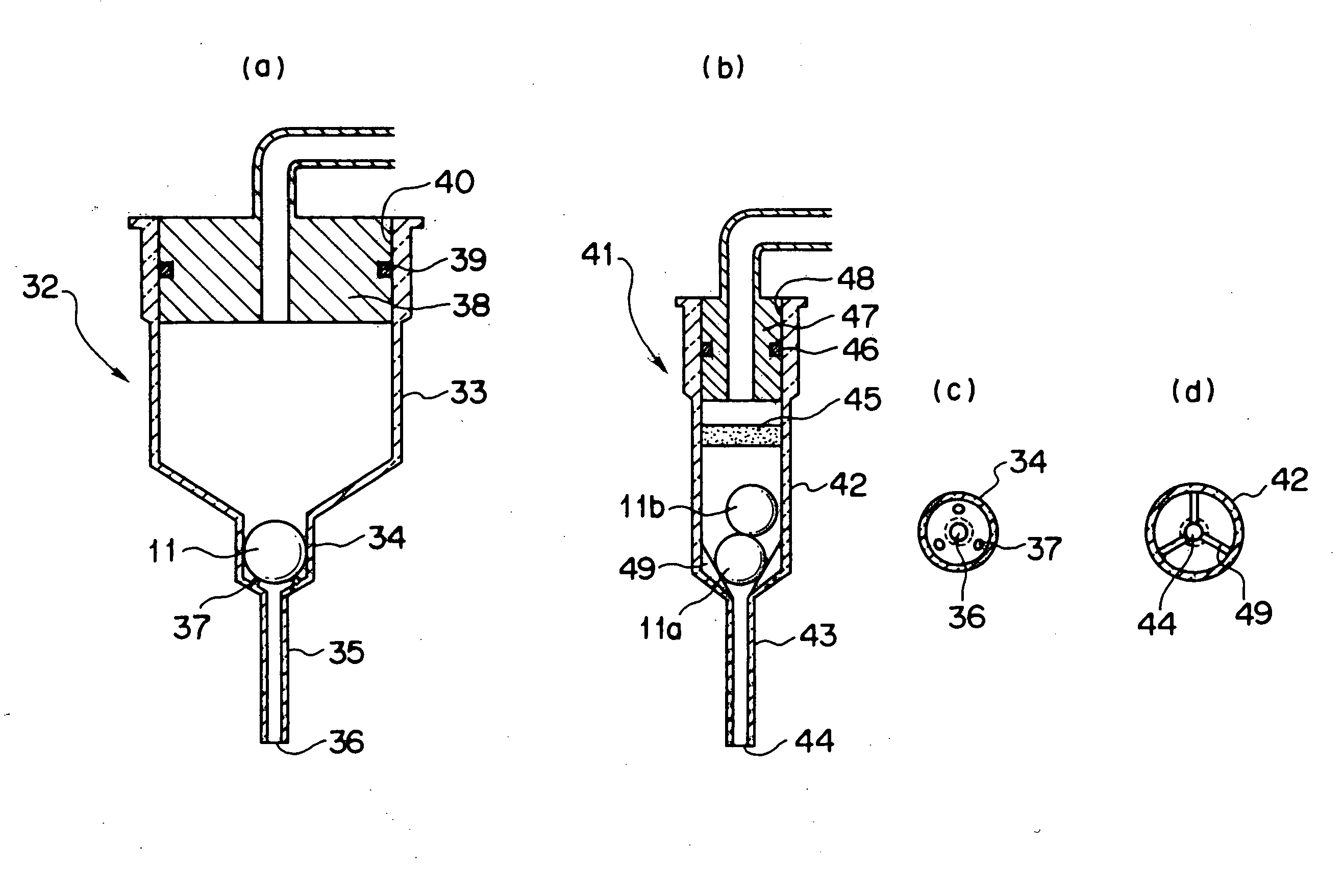
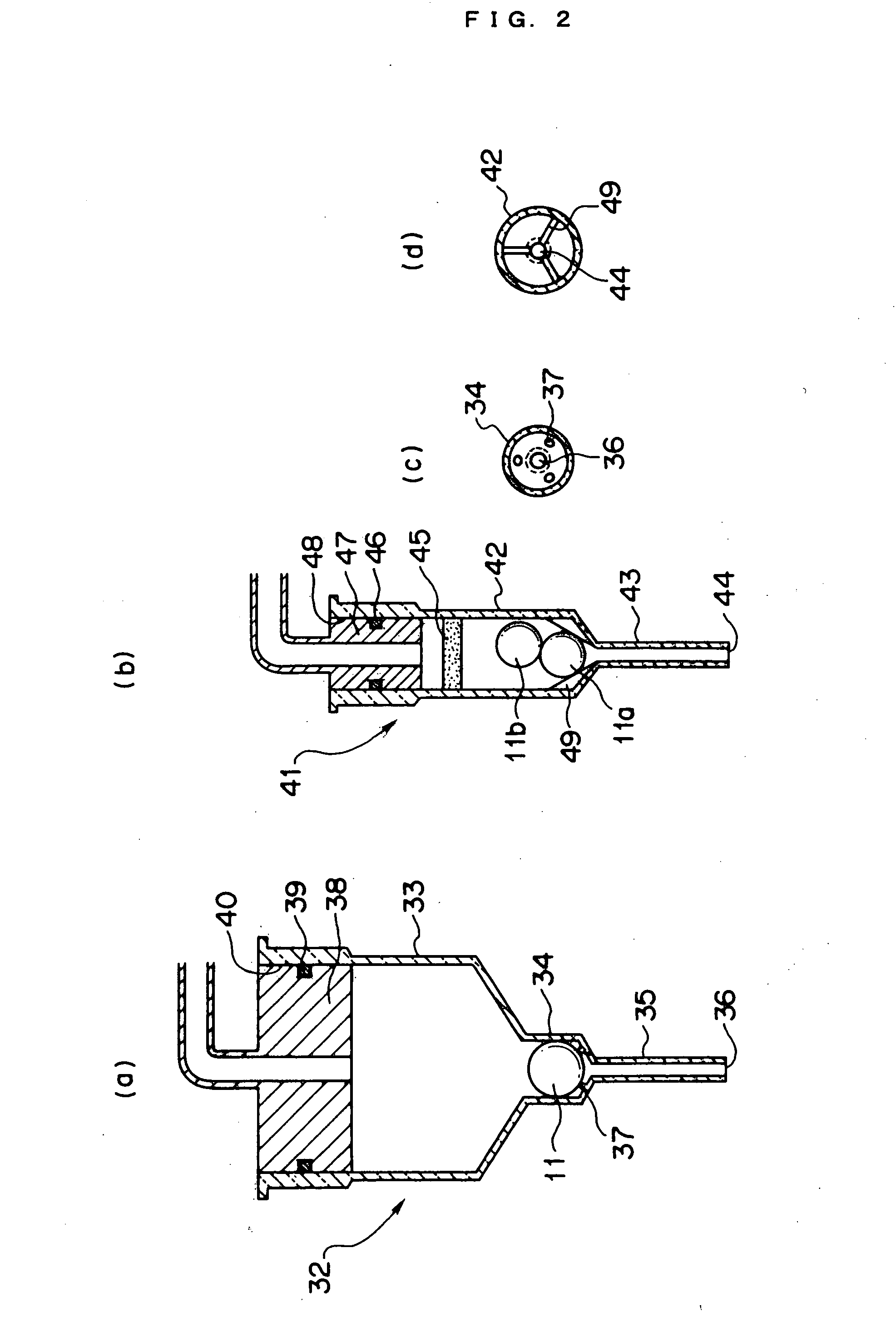
[0074]FIG. 2(a) and (c) show an example of a carrier housing section 32 according to a

[0075] The carrier housing section 32 is approximate cylindrical having approximate three steps accommodating the spherical carrier 11 inside. The carrier housing section 32 has a fluid inlet / outlet 36, and is fitted to a nozzle section 38 of a drawing / discharging section which draws and discharges a fluid with respect to the carrier housing section 32, passing through the inlet / outlet 36. Moreover it is possible to transfer the inlet / outlet 36 of the carrier housing section 32 relatively with respect to a container (not shown) provided outside, by a transferring section (not shown).

[0076] The carrier housing section 30 has a large diameter section 33 which is able to accommodate a fluid, with its opening 40 fitted to the nozzle section 38 via an O-ring 39, a small diameter section 35 which has the inlet / outlet 36 at the tip and has a smaller diameter than the large diameter section enabling inser...

third embodiment

[0078]FIG. 2(b) and (d) show an example of a carrier housing section 41 according to the

[0079] The carrier housing section 41 is approximate cylindrical having substantially two steps accommodating two spherical carriers 11a and 11b. The carrier housing section 41 has a fluid inlet / outlet 44 and is fitted to a nozzle section 47 of a drawing / discharging section which draws and discharges a fluid with respect to the carrier housing section 41, passing through the inlet / outlet 41. Moreover it is possible to transfer the inlet / outlet 44 of the carrier housing section 41 relatively with respect to a container (not shown) provided outside, by a transferring section (not shown).

[0080] The carrier housing section 41 has a large diameter section 42 which is able to accommodate a fluid, with its opening 48 fitted to the nozzle section 47 via an O-ring 46, and a small diameter section 43 which has the inlet / outlet 44 at the tip and has a smaller diameter than the large diameter section enabli...


PUM

PropertyMeasurementUnit
sizeaaaaaaaaaa
self-weightaaaaaaaaaa
frictional forceaaaaaaaaaa

Abstract

An object is to provide a carrier housing/processing apparatus and a method wherein complicated reaction processes are simplified, and the processes can be easily performed with a small scale apparatus structure. The construction comprises; one or a plurality of carriers fixed or able to be fixed with chemical substances such as ligands; a carrier housing section which is provided with a fluid inlet/outlet and which accommodates the carrier; a drawing/discharging section which draws and discharge a fluid through the inlet/outlet with respect to the carrier housing section; and a transferring section which transfers the inlet/outlet relatively with respect to containers provided outside. Moreover, the carrier is formed in a size or a shape not allowing the carrier to pass through the inlet/outlet, and in a state of holding the carrier in the housing section, by self-weight of the carrier, frictional force between the carrier and the inner wall of the housing section, or remote force from outside with respect to the carrier, a fluid is drawn and discharged.

Description

CROSS REFERENCE [0001] This application is a United States national phase application of co-pending international patent application number PCT / JP03 / 00316, filed Jan. 16, 2003, which claims priority to Japanese patent application number 2002-9218, filed Jan. 17, 2002 which priority is claimed.TECHNICAL FIELD [0002] The present invention relates to a carrier housing / processing apparatus and its method. The present invention relates to all manner of fields which require the handling of biological high / low molecular weight compounds such as genes, immune systems, amino acids, proteins and sugars; including for example the fields of engineering, agricultural science incorporating foodstuffs, agricultural production and seafood processing, pharmaceuticals, medical fields incorporating hygiene, health, immunity, disease and genetics, and scientific fields such as chemistry and biology. [0003] In particular, the present invention is an effective method in the case where a series of process...

Claims


Application Information

Patent Timeline
Patent Type & Authority Applications(United States)
IPC IPC(8): B01L3/02C07H21/04C12M1/00C12M1/34C12N15/00G01N33/50G01N35/00
CPCB01L3/0275G01N2035/00574B01L2300/0681B01L2300/0636C12M1/40C12M1/00C12N15/00G01N33/50
Inventor TAJIMA, HIDEJI
Owner PRECISION SYST SCI
Why Eureka
Try Eureka