Method and equipment to divide glass plates into cut pieces

a technology of glass plates and cutting pieces, applied in the direction of paper/cardboard containers, lighting and heating apparatus, containers, etc., can solve the problems of entail further processing delays, substantial drawbacks, conversion or adaptation may entail further delays, etc., and achieve the effect of reducing the transit time of different glass types very substantially

Inactive Publication Date: 2007-08-14
ALBAT WIRSAM SOFTWARE VERTRIEBSGES
View PDF23 Cites 11 Cited by
  • Summary
  • Abstract
  • Description
  • Claims
  • Application Information

AI Technical Summary

Benefits of technology

[0013]The objective of the present invention is to overcome the drawbacks of the state of the art, to very considerably reducing the space required to sort glass cut-pieces in the interim buffer, and to significantly reduce the transit times of different kinds of glass. Accumulation of residual glass shall be extensively averted and the handling of such residues shall be considerably reduced. Moreover the method of the invention overall shall react in flexible manner to malfunctions and shall always assure rational manufacture even of small lots.
[0015]In this manner sub-plates of different glass types are supplied constantly (sub-plate dispensers) which may be made available in tight time sequences and as called for are processed further. If illustratively pairs of panes of different material properties are needed, then this need may be rapidly and conveniently met by inserting sub-plates of the corresponding material properties in alternating manner into the sequence of sub-plates. First one sub-plate of the first glass type shall be separated and stored in the interim buffer. During this time the ensuing sub-plate of the other glass type already may be cut. As soon as the desired panes meet in the interim buffer, they may be immediately fed to the subsequent processing for instance of an insulating glass line. No longer is it necessary to fully divide an entire stocked plate. Instead the interim buffer shall be constantly emptied. As a result the space required to sort the finished cut pieces in the interim buffer is very considerably reduced, with only advantageous consequence on the costs of production. Again the dwell time of the particular cut pieces in the interim buffer is substantially shorter than in the known methods and as a result the further processing may be rationalized further.
[0016]Another advantage of the method of the invention, which may be fully automated by a program control unit, is that the transit times are significantly shortened. As a result malfunctions during optimization and / or within the further processing may be dealt with rapidly and flexibly, namely by the program control unit inserting for instance a pane required for rapid action within the sequence of sub-plates. Even smaller lots of one glass type always may be rationally sub-divided and be incorporated into an ensuing manufacture. The remaining optimizing operation is hardly interfered with on that account because the particular sub-plates did transit in minimal time.
[0017]The method of the invention indeed offers more than only good cutting rates. On the contrary sequences may be attained during cutting that assure optimal input to the further processing by means of the interim buffer dynamics. Even in the presence of a daily mix of 5 to 6 kinds of glasses, the method of the invention allows synchronizing the optimizations of the particular kinds of glasses while the required space in the interim buffer always remains minimal.
[0022]In surprisingly simple manner, the intermediate storage allows rapid and direct access to glass plates of different kinds of glasses. At the end of the cutting and breaking-off line, pairs or groups of panes may be constituted rapidly and in targeted manner in the interim buffer and the pairs may be directly processed further. As a result the required bulk in the interim buffer is substantially reduced over the case of the state of the art. At the same time the transit times of different glass kinds are very substantially reduced.

Problems solved by technology

This known glass cutting procedure incurs the substantial drawback that the full volume of one kind of glass must be continuously worked off in relation to the cutting agenda calculated by the cut-piece optimizing program, that is, only after a lot size on the average of 400 m2 of individual glass has been entirely cut to size and without interruption will it be feasible to further process this production lot according to a sequential process.
Such a wait may be as long as half a day and may entail delays in the further processing.
Another problem is incurred in that at the end of an optimizing run, an often substantially large residual plate shall remain on the cutting table and must be eliminated from the procedure by means of the tipping table or manually, before another kind of glass may be cut.
Re-using such a residual plate in a sequential process most of the time is possible only by incurring substantial difficulty because of interference with the optimizing runs.
Such conversion or adaptation may entail further delays.
Accordingly a glass rupture or a high-speed event occurring in further processing can be cut only outside the conventional logic and hence in much time-delayed manner.
The cost in labor is commensurately high, also the manufacturing costs.
Such a procedure is hardly suitable for rationalized mass production.
The multiple production of substantially large panels however is just as problematical as the processing of different kinds of glass because the residual pieces always resting on the pane support require either being used according to some priority or being removed individually out of the cutting apparatus, thereby commensurately increasing the cost in time and labor.
The procedure for continuously feeding the manufacture of panes of insulating glass is commensurately unsuitable.

Method used


Image

  • Method and equipment to divide glass plates into cut pieces
  • Method and equipment to divide glass plates into cut pieces
  • Method and equipment to divide glass plates into cut pieces

Examples


Embodiment Construction

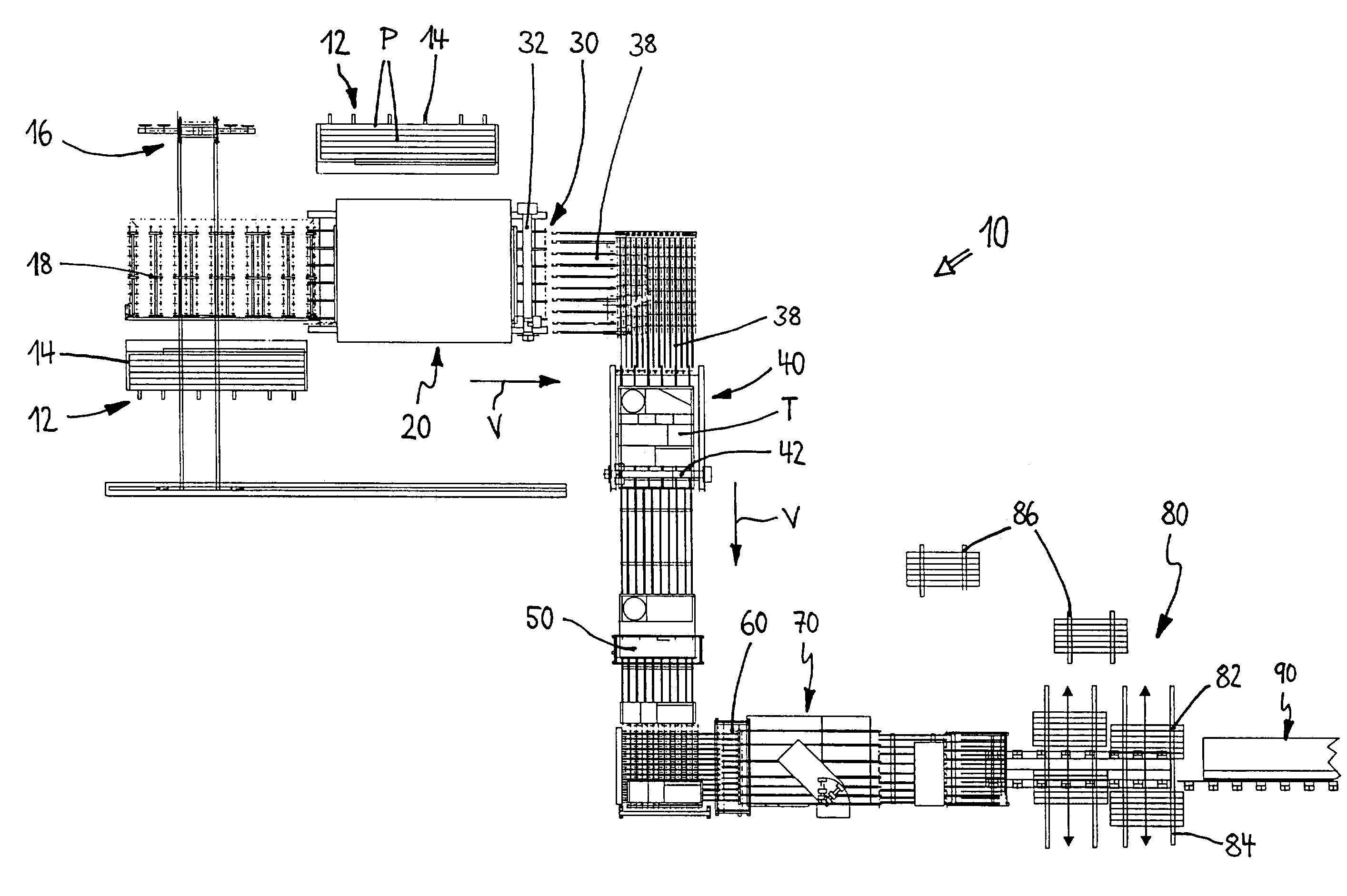
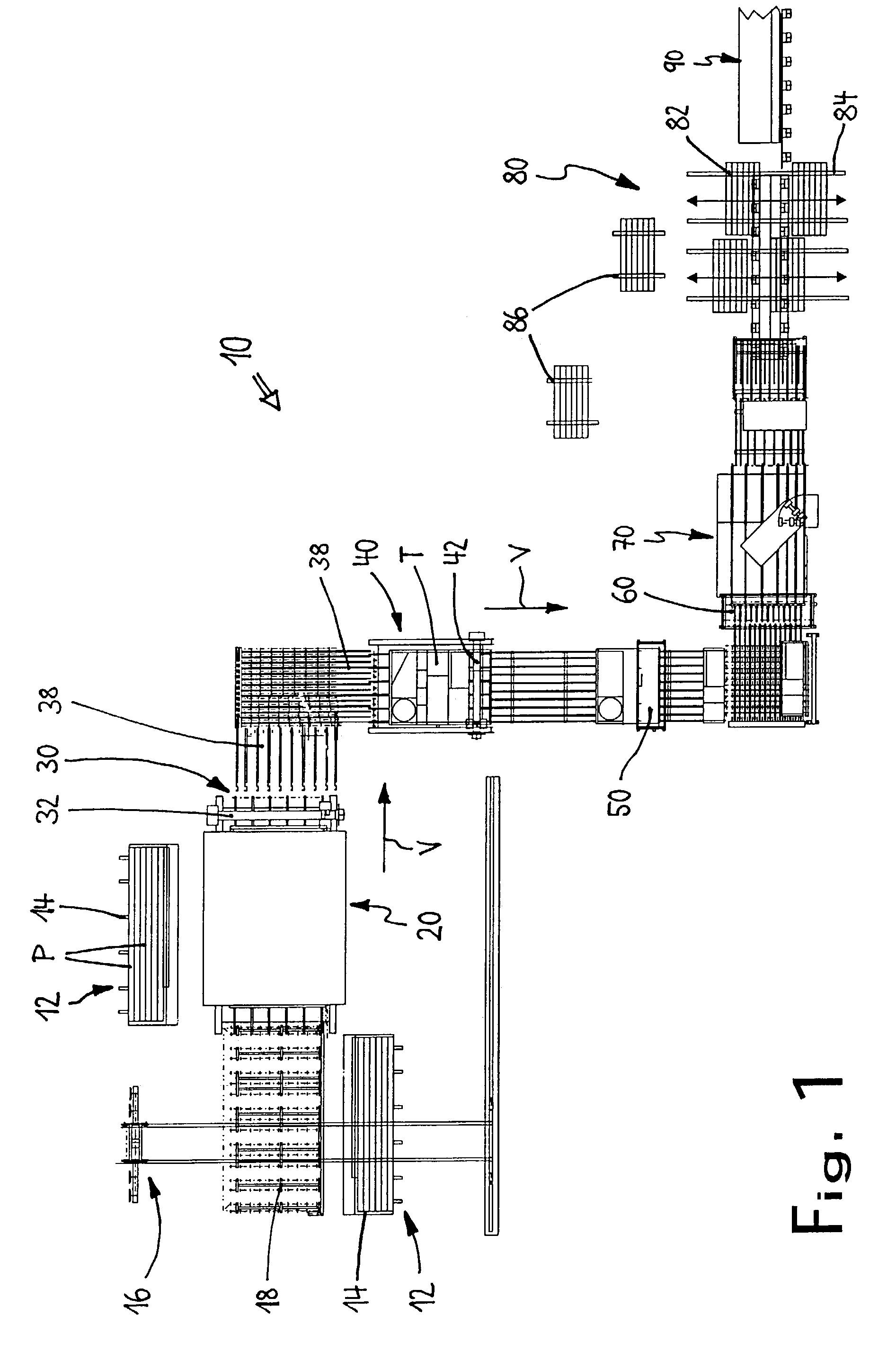
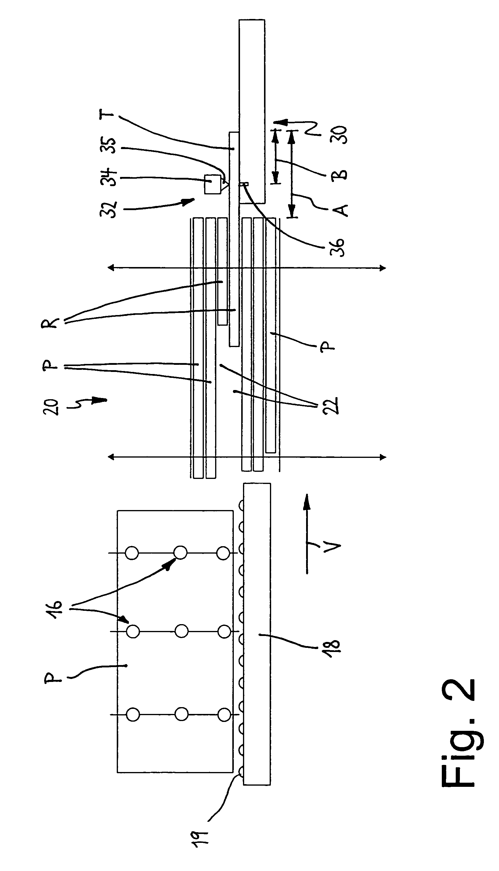
[0028]The equipment generally denoted by 10 in FIG. 1 is used to divide glass plates into cut pieces and comprises a blank-plate storage 12 loaded with blank plates P which rest in packets distinguished by material properties on A or L frames 14. Material properties illustratively mean different glass thickness, kind and design of coating or improvement, tinting, color etc. The sizes of the glass plates P are about 6,000×3,210 mm. A removal system 16, for instance a portal crane, is able to access each individual glass plate P in the plate storage 12. Said plates are picked up by omitted vacuum suction means and then are deposited consecutively and horizontally on a deposition table 18.

[0029]The plates P are moved from the deposition table 18 to an intermediate storage 20 using rollers 19. The intermediate storage is designed in magazine-like manner with several superposed receiving compartments 22. Each receiving compartment 22 is associated to a predetermined kind of glass, and up...


PUM

PropertyMeasurementUnit
sizesaaaaaaaaaa
areaaaaaaaaaaa
thicknessaaaaaaaaaa

Abstract

A method of dividing glass plates for the purpose of reducing the required space in an interim buffer (80) reducing the transit times of different kinds of glasses, comprises generating a sequence of sub-plates (T) from the glass plates (P) stored in a blank plate storage (12), the consecutive sub-plates (T) of the sequence of sub-plates exhibiting identical or different material properties. Each sub-plate (T) is subdivided further by scribing and breaking-off until a desired cut piece has been attained. The generated cut pieces are deposited in a predetermined order in the interim buffer (80) and as called for are processed further. Equipment dividing glass plates into cut pieces accordingly entails that different cutting and breaking-off systems are preceded by at least one intermediate storage receiving at least two glass plates exhibiting different material properties and delivering a programmed sequence of sub-plates, the consecutive sub-plates exhibiting identical or different material properties.

Description

FIELD OF THE INVENTION[0001]The present invention relates to a method for dividing glass plates into cut pieces, and to equipment for practicing the method.BACKGROUND ART[0002]When cutting many common glasses to fixed sizes, the starting point as a rule shall be a glass plate of about 6,000×3,210 mm. The raw material is delivered on large A frames and is stored in sets on A or L frames in an uncut plate storage facility. Each glass plate is removed from among the sets at the storage facility by means of a portal crane or by other means and then is transferred to tipping table. By means of vacuum suction devices, said table moves the glass plate from the vertical into the horizontal position.[0003]The glass plate moves from the tipping table onto a cutting table where it is properly positioned and then locked in place. This cutting table is fitted with a usually rotatable cutting head mounted on a two-dimensionally displaceable bridge and able to move in both directions and hence to ...

Claims


Application Information

Patent Timeline
Patent Type & Authority Patents(United States)
IPC IPC(8): B65H35/10B26D3/08B65G49/06C03B33/03
CPCB65G49/068C03B33/03B65G2249/04Y10T225/307Y10T225/12Y10T225/325Y10T225/321Y10T83/0591Y10T83/0341
Inventor WIRSAM, BERND
Owner ALBAT WIRSAM SOFTWARE VERTRIEBSGES
Why Eureka
Try Eureka