
Computerized simultaneous laser marking and targeting system

a laser marking and laser marking technology, applied in the field of computerized simultaneous laser marking and targeting system, can solve the problems of label becoming obsolete, method restrictive, label being difficult to read, etc., and achieve the effect of reducing the risk of human error and avoiding wrongful processing

Inactive Publication Date: 2005-06-16
ZOLTAN FILEP
View PDF10 Cites 8 Cited by
  • Summary
  • Abstract
  • Description
  • Claims
  • Application Information

AI Technical Summary

Benefits of technology

[0003] The invention is directed to increase the efficiency of existing laser marking and targeting systems, helping also decision making and process control.
[0006] Decision making can be aided by image recognition software working together with at least one database. This can reduce the risk of human error, avoiding wrongful processing like friendly fire or civilian casualties.
[0007] The differences from the classical “point the target” procedure to the simultaneous targeting are like from the sequential search of information on magnetic bands to the direct memory access on hard-drives, the advantages are undeniable.

Problems solved by technology

The method is restrictive, because the object has to be oriented all the time towards the scanners, otherwise the labels cannot be read.
After a certain processing phase, the label may become obsolete, creating confusion.
Handling of large size of objects makes the classical method of marking also too slow.
There are other fields, like in the military, where marking is also important - making difference between target and neutral or even friendly objects, but labeling is impossible.
Classical laser targeting is sequential, one object after the other, where the targeting has to follow the target until processing, making parallel processing impossible.

Method used


Image

  • Computerized simultaneous laser marking and targeting system
  • Computerized simultaneous laser marking and targeting system
  • Computerized simultaneous laser marking and targeting system

Examples


Embodiment Construction

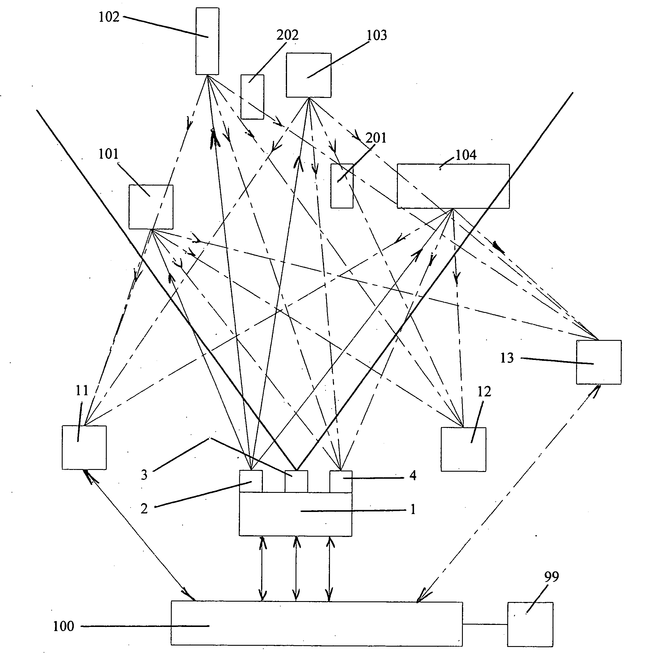
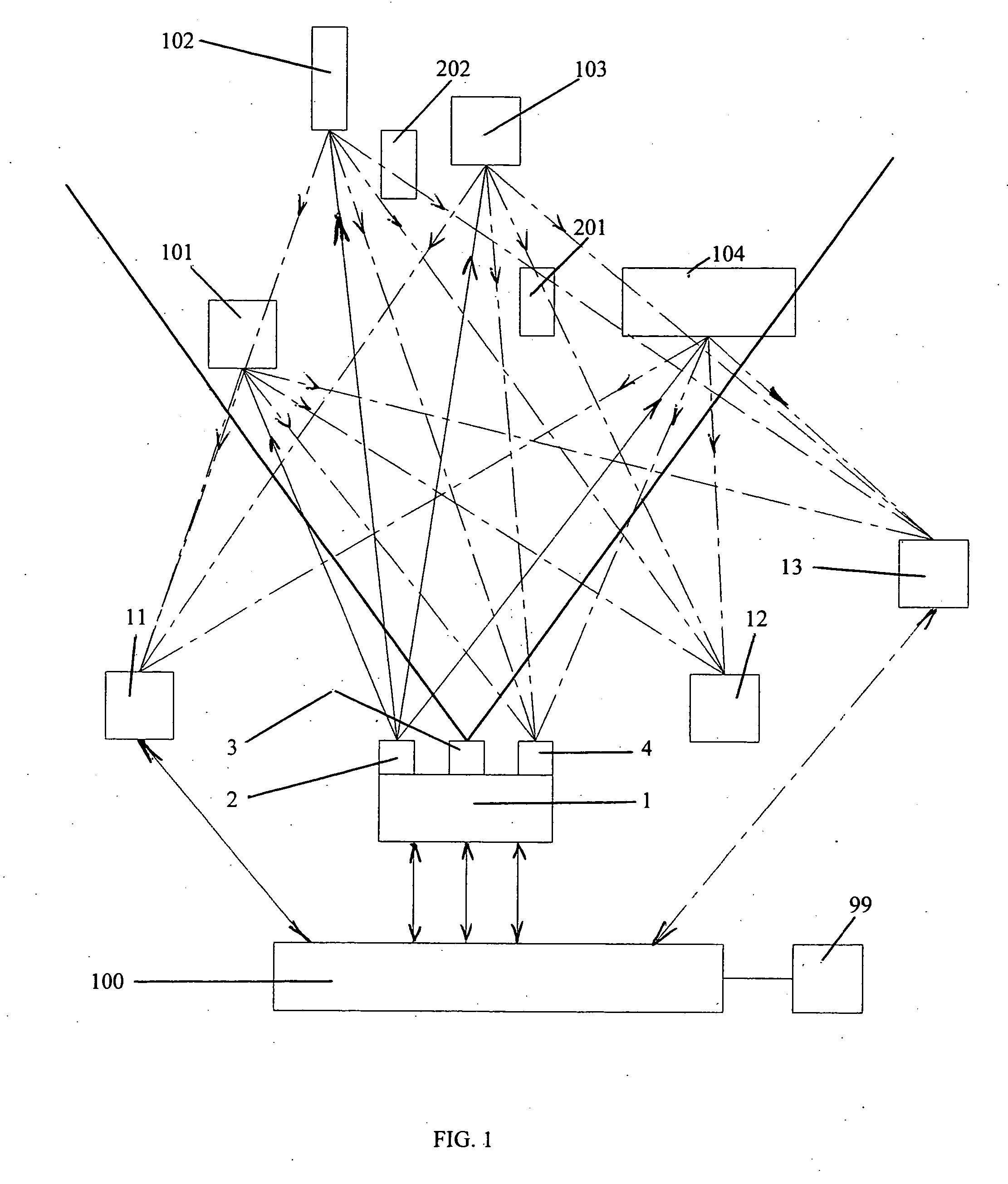
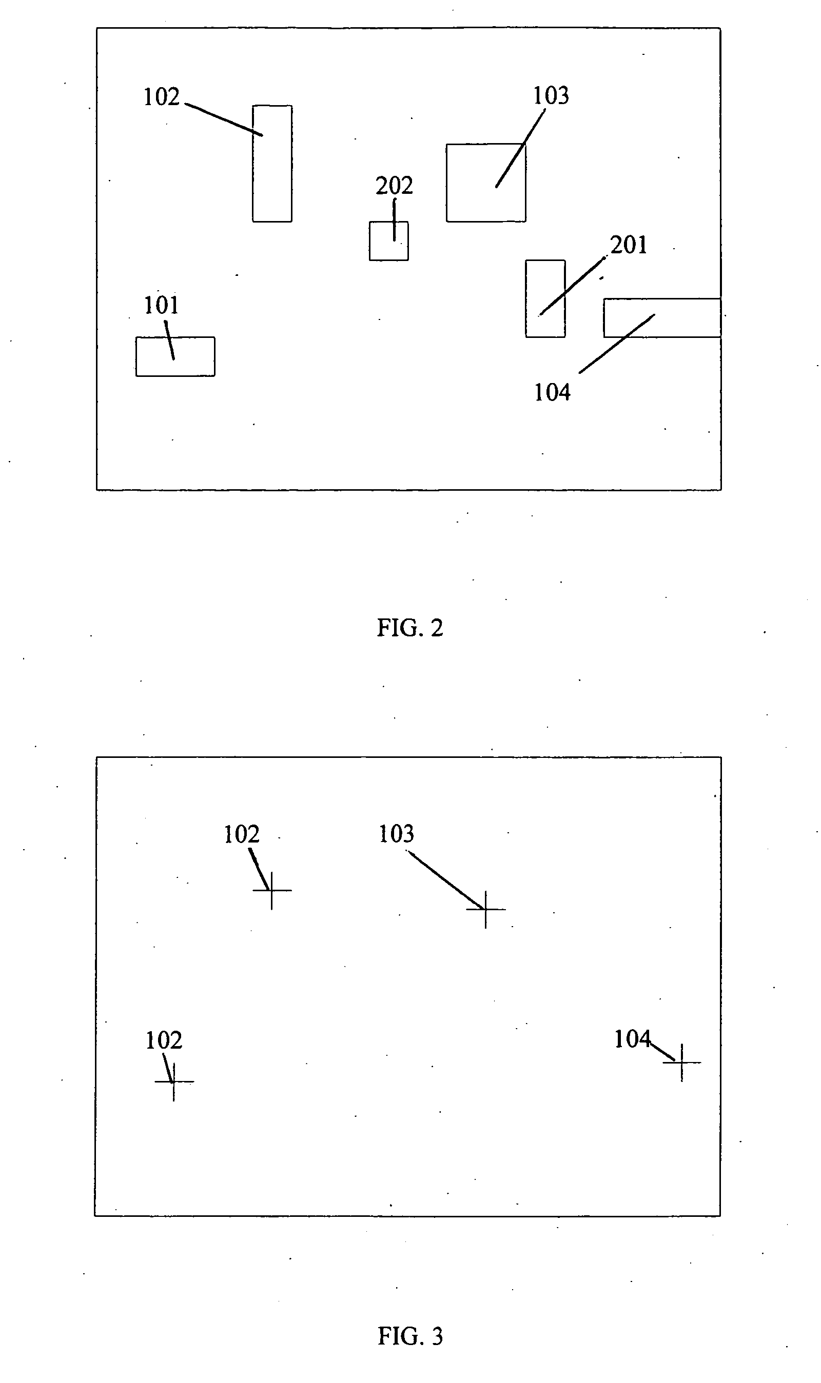
[0015] In all drawings: [0016]1 Simultaneous Laser Targeting equipment (SLT) [0017]2 Simultaneous Laser Targeting Unit (SLTU) [0018]3 Video Camera (VC) [0019]4 Laser Control Camera (LCC) [0020]11, 12, 13—Processing Units (PU) [0021]101, 102, 103, 104—Target Objects (TO) [0022]201, 202—Neutral Objects (NO) [0023]100—Computer [0024]99—Human Machine Interface (HMI) [0025]501—SLTU Controller [0026]511—Laser [0027]512—Laser Control Unit [0028]521—Rotating Mirror [0029]522—Horizontal Servo Motor [0030]523—Vertical Servo Motor [0031]601, 602, 603, 604—Guiding Sensors [0032]605—Selector Sensor

[0033]FIG. 1 is a general view of the application of the invention as a targeting system. From a multitude of objects, 101—104 are selected as target. The rest of the objects -201 and 202—are considered neutral and are not targeted. Targeting is executed by 1, the SLT.

[0034] The simultaneous laser targeting equipment 1 (SLT) has as components the simultaneous laser targeting unit 2 (SLTU), the video ...


PUM


Abstract

What is new in this invention, it is the complete automation of the remote marking process. It is completely computer controlled and made possible by laser printer type marking / pointer equipment. Also, completely new is the concept of embedding digital information into a laser beam or other coherent information vector and attaching this way data / information to any object or place. New is the idea of using a discrete information vector not only as a beacon but also as a selector for the marking of more than one target objects. New is the idea of completely software controlled computerized digital marking of places or objects for closing motion control loops. No on-site human operators / soldiers needed. No position sensors needed anymore, nothing is bolted down, easy to reconfigure any environment. The invention is a major step in robotics and controls, improving considerably the eye-hand coordination of robots, making fully possible the action of the digital world on the real / physical world. A novel method and system is provided for simultaneous, non-invasive and non-contact marking for processing of targeted objects. The viewing, selection, marking, processing and feed-back is simultaneous and computerized.

Description

BACKGROUND OF THE INVENTION [0001] Marking is an important component in the processing of objects. Marking is actually communicating information and decisions to the processing units. Even for a temporary marking, like for a processing phase, labeling and scanning has been used. The method is restrictive, because the object has to be oriented all the time towards the scanners, otherwise the labels cannot be read. After a certain processing phase, the label may become obsolete, creating confusion. It needs additional equipment and time in the processing flow for this type of marking. Handling of large size of objects makes the classical method of marking also too slow. Labels can be read one at a time, slowing down the parallel processing. [0002] There are other fields, like in the military, where marking is also important - making difference between target and neutral or even friendly objects, but labeling is impossible. Classical laser targeting is sequential, one object after the ...

Claims


Application Information

Patent Timeline
IPC IPC(8): G01B5/20
CPCF41G3/145F41G7/2233G01S17/66F41G7/2266F41G7/2293F41G7/226Y10S33/21
Inventor FILEP, ZOLTAN
Owner ZOLTAN FILEP
Learn More