
Pneumatic boat arranged for the loading/unloading and transportation of floating loads

a pneumatic boat and load-loading technology, applied in the field of pneumatic boats, can solve the problems of large installation of transportation devices, and achieve the effects of low cost, simple design and low manpower

Active Publication Date: 2005-06-16
ZODIAC MILPRO INT
View PDF4 Cites 13 Cited by
  • Summary
  • Abstract
  • Description
  • Claims
  • Application Information

AI Technical Summary

Benefits of technology

[0005] An object of the invention is thus to propose an original solution to the problem posed, with a boat specially fitted out to allow the loading / unloading of a floating load under simple implementation conditions, and even with the aid of less manpower (for example by just one person), this boat itself being of simple design and relatively inexpensive to manufacture.
[0016] Thus, by virtue of the arrangements in accordance with the invention, a simple boat is constructed, said boat not having a motor (no rear board) and designed to be towed (“sled” boat), which, owing to the marked nose-up and partially submerged position that it is able to occupy, can be loaded very easily, as the floating load is brought closer to and held against the floor of the boat while the latter is set afloat.
[0017] Furthermore, owing to its very concept, a boat of this type may be designed on the basis of existing semi-rigid-type pneumatic boats, from which it can take essential elements: the boat according to the invention may thus be produced at lower cost.
[0018] However, bearing in mind some of its basic characteristics, the boat according to the invention may be made to be different by means of specific arrangements. In particular, owing to the absence of a motor, the rigid underwater hull and the floor may be extended towards the rear, substantially as far as the vicinity of the rear ends of the floats to provide a maximum surface area for supporting the load when the latter is on board.
[0019] So that the boat can occupy a nose-up, partially submerged position suitable for best facilitating the loading / unloading operation, it is advantageous for the ballast to occupy substantially the rear half of the rigid hull and for the two rear chambers of the floats to preferably have substantially the same length as the ballast. Furthermore, in order for the boat to remain sufficiently buoyant despite the ballast being filled with water and the rear part of the two floats being deflated, it is desirable for the front part of the rigid hull not occupied by the ballast to be filled with a low-density material (buoyant material).
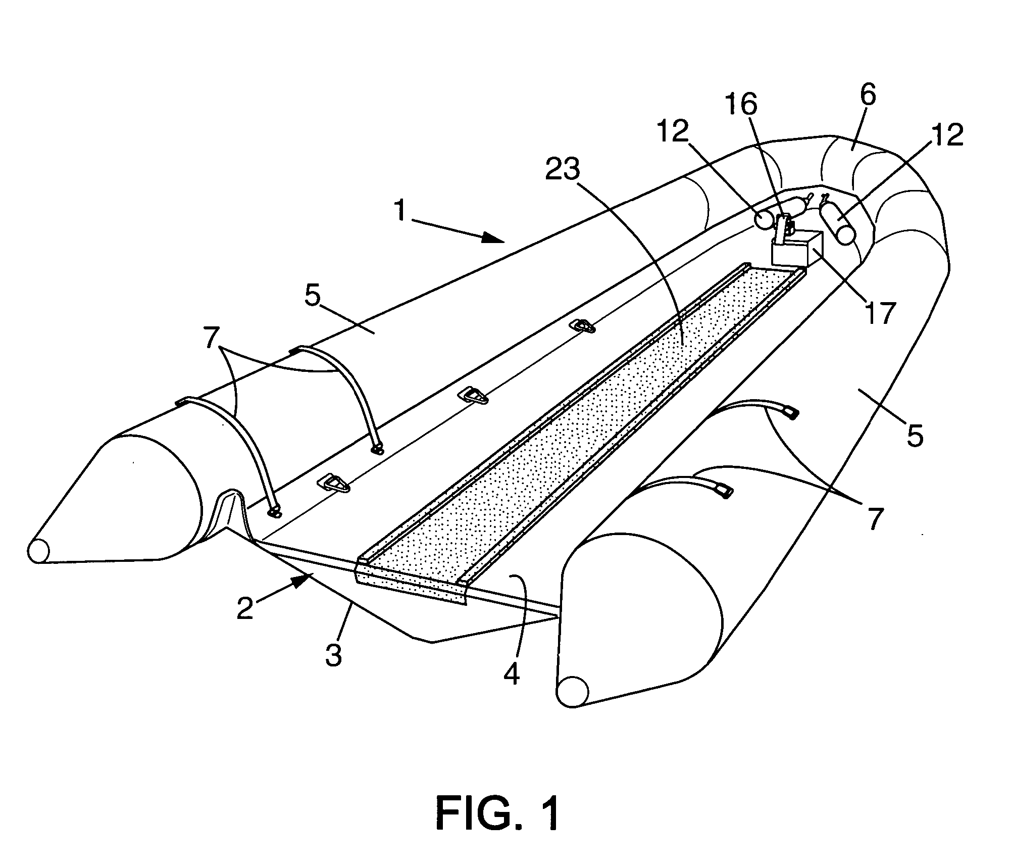
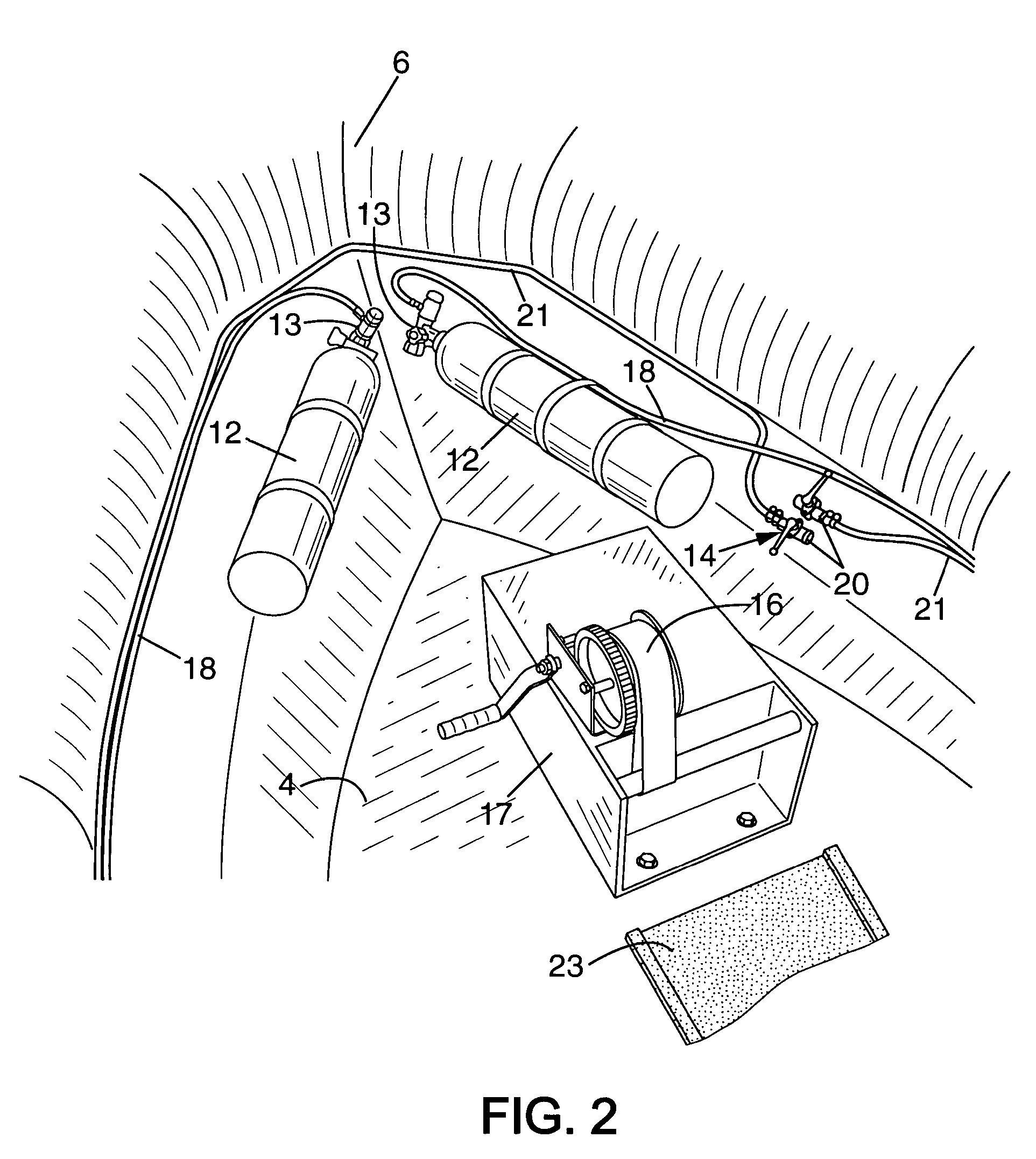
[0024] Furthermore, it is advantageous for the inflating means and the deflating means to have their respective controls located at the bows of the boat, in the vicinity of said box structure, such that one person alone, located at the bows and having all the controls within arm's reach, can fully handle the boat.

Problems solved by technology

However, such transportation devices are known for handling bulky, heavy floating loads such as ships that cannot be moved by conventional means, and these transportation devices are very sizeable installations.
There is currently no equivalent for handling floating loads of lesser volume and less weight (for example floating tanks, marker buoys, small craft, animals, etc.) without such loads being handled with the aid of on-board cranes, which is a restrictive solution.

Method used


Image

  • Pneumatic boat arranged for the loading/unloading and transportation of floating loads
  • Pneumatic boat arranged for the loading/unloading and transportation of floating loads
  • Pneumatic boat arranged for the loading/unloading and transportation of floating loads

Examples


Embodiment Construction

[0032] In the following description, reference will first be made to FIGS. 1 to 4.

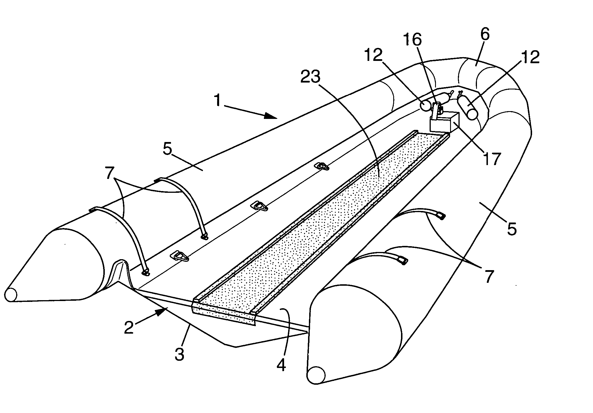
[0033] The boat according to the invention, for transporting floating loads, is a pneumatic boat of the general type known as a semi-rigid boat 1, which includes a rigid hull 2 defined by a rigid underwater hull 3 closed on the top by a rigid floor 4 and bordered at least on two sides by two pneumatic floats 5. In general, the two floats 5 join up towards the bows at 6, above the stem of the underwater hull.

[0034] Unlike a traditional semi-rigid boat, the boat according to the invention has no rear board and thus no motor. Globally, therefore, it takes the form of a simple barge, as may be seen best in FIG. 1. Furthermore, owing to the absence of a motor, the rigid hull may be extended towards the rear substantially as far as the vicinity of the rear ends of the floats 5, such that the floor 4 has a maximum surface area.

[0035] The assembly of floats 5 may be fastened to the rigid hull 2 by any means...


PUM


Abstract

A semi-rigid pneumatic boat (1) comprising: a rigid hull (2) defined by a rigid underwater hull (3) closed on the top by a rigid floor (4) and bordered on two sides by two pneumatic floats (5); a ballast (8) arranged in the rear part of the rigid hull (2) and pumping means for filling it with water or emptying it thereof; two pneumatic chambers (10) defined in the respective rear parts of the two floats (5) and pneumatically isolated from the rest of the floats; means (12, 13) for inflating and means (14) for deflating the rear chambers; the boat having no rear board; thus, by filling the ballast (8) and by deflating the rear chambers (10) the boat is nosed up, with its rear part submerged and a load (25) may be brought closer, against the floor (4), and then by emptying the ballast and re-inflating the chambers (10) the boat is set afloat, supporting the load (25).

Description

FIELD OF THE INVENTION [0001] The present invention relates to the field of the transportation of floating loads, and relates more particularly to a pneumatic boat of the semi-rigid type comprising a rigid hull defined by a rigid underwater hull closed on the top by a rigid floor and bordered at least on two sides by two pneumatic floats. DESCRIPTION OF THE PRIOR ART [0002] For transporting floating loads such as ships or the like, it is known to have recourse to transportation devices of the “floating-dock” type, which includes ballasts that can, as desired, be filled with water in order to at least partially sink the transportation device and to bring the floating load in line with it (loading) or to move the floating load away from it (unloading), or filled with air in order to make the transportation device float and to cause it to rise up under the floating load in such a way that it can take up said load and move it. [0003] However, such transportation devices are known for ha...

Claims


Application Information

Patent Timeline
Patent Type & Authority Applications(United States)
IPC IPC(8): B63B7/08B63B27/00B63B27/36B63B35/42
CPCB63B7/082B63B27/36B63B13/00B63B27/19
Inventor BOUQUARD, PASCAL
Owner ZODIAC MILPRO INT
Learn More